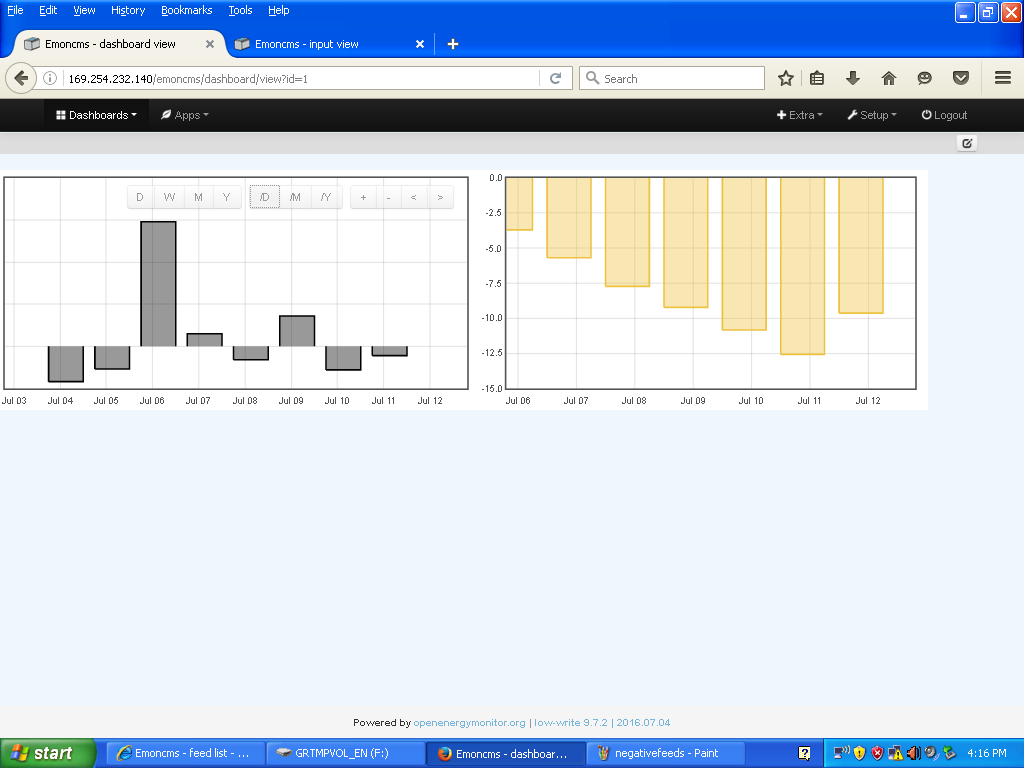
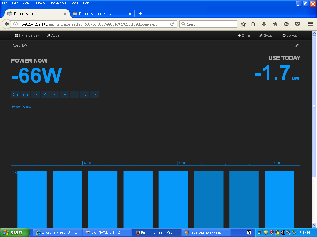
I had negative lecture about my energy usage
I had a 3mm-4mm neutral face , here is the CT sensor connected
I had negative lecture about my energy usage
I had a 3mm-4mm neutral face , here is the CT sensor connected
Please write in your own language. Your translation uses the wrong words, and I do not completely understand your problem.
Did you install the C.T. according to the instructions here?
hola
si he siguido las instrucciones , he girado el clip CT , y ahora tengo lectura positive , pero los graficos siguien visualizandose con las barras invertidas , I aun no es possible configurar el api feed desde emoncms.org
That is correct. Turning the CT around will change the real power from negative to positive.
I understand that you want to change the bargraph that was negative. That is not possible without editing the database manually. All you can do is delete the Feed and start again. The bars will now be above the line - unless you generate your own electricity and generate more than you use, then the power will again be negative. We say imported power is positive, exported power is negative.
thanks I ll try
Similar here. I run a heatpump and I only monitor that individual device. It is a single phase 25 amps machine. In its’ monitoring mode it reads 10 - 17 watts of NEGATIV power. When it starts do it’s thing (mostly heating water in this time of the year) it than produces postive results.
I switched the clip around and now things are reversed ofcourse.
Here is my question - is this a measuring problem or a heatpump / installation problem or have a missed out on piece of information on the openenergy monitor hardware. Clearly the heatpump requires power to monitor itself so i would expect that both readings (i.e. monitoring + production) would be either postive or negative.
I think what you are seeing there is a result of phase error around the PF of an inductive circuit eg a motor.
I see a similar effect on some of my installs that monitor some heat recovery and ventilation systems, the rest of the monitored circuits “appear” ok just the CTs that monitor the ventilation fans give a negative power consumption at rest and read pretty accurately when running.
I assume this could be reduced by calibrating each ct channel in situ with a purely resistive load, but this is not always practical in the real world, I do not do all my installs and it is hard enough to do let alone attempt to train a contract electrician to do it, so I have had to opt for a approximate phasecal and accept the error until we can automate the phase calibrations (something I have toyed with but not achieved yet).
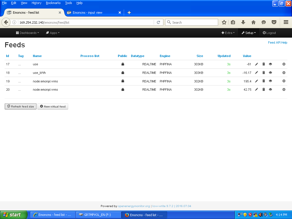
It can however, be easily removed in emoncms with an “allow positive” process.
What hardware are you using to make the measurement?
Are you measuring real power or apparent power? (i.e., do you have an a.c. adapter connected and reading correctly?)
So would I. But if you are measuring real power and in standby mode the heat pump appears to be a true capacitor (or very nearly), then a small error in the phase angle correction could well mean that the current phasor has moved into the next quadrant and crossed the imaginary axis, from positive real power to negative real power.
Then when the load comes on, the power factor of the heat pump becomes much closer to 1 and the error is masked.
I don’t think your heat pump can actually generate electricity, so I think it is not a problem with the heat pump itself.
[Grr… Paul got there first, but we’re saying the same thing.]
How can apparent power go negative?
Easily - a faulty algorithm or a coding error, or a mistaken “correction”.
We have no idea what @Antoine_Maartens is actually using. All we know is there’s a heat pump and some means of measuring a quantity and the numbers coming out are called power. If it’s not our hardware and a standard sketch, it’s anyone’s guess what’s going on - it could be faulty maths somewhere, something in emonCMS, who knows? If it is apparent power and it’s going negative, that does reduce the area that needs scrutiny (unlikely, but I’ve been caught out by things like that before, hence the scepticism).
HW = emonbase + emontx with clamp around the phase cable. Heatpump has dedicated breaker. I measure just after the breaker.
I get these resultaat from the Standard log to feed algorithm.
Please let me know What other specs you need.
Thanks for the input so far!!!
and is it the Euro adapter from the OEM Shop?
Is it the YHDC SCT-013-000 current transformer from the OEM Shop? Does it have a moulded-on plug?
Did you calibrate the emonTx yourself or is the sketch not changed from the one loaded at the factory?
This heatpump is an 8 kW Fujitsu-siemens waterstage. It is hard wired into my home’s powersupply. I therefore can not double check the measurements in emoncms with a watt meter. I can provide a picture if that is helpful.
All elements in the monitoring process are straight out of the box of the OEM-shop.
I did not calibrate. The thing I added to the configuration was the API key to load data into emoncms.org.
I use the 4,5kW max port (=CT4) on the emonTx box.
Here are my own thoughts (sorry, I’ am a newbie in this hardware domain.)
If that was easy, it might confirm what we suspect, but as it is difficult or not possible, don’t worry about it.[quote=“Antoine_Maartens, post:13, topic:975”]
Could it be that the internal unit of the heatpump monitors the external unit and that therefore a negative current exists?
[/quote]
I don’t think so. The heat pump uses electrical energy to extract heat from the environment and move it into the house. The only way that you can get a true negative power flow is if you generate electricity, say with PV or a water or wind turbine, or a standby diesel generator![quote=“Antoine_Maartens, post:13, topic:975”]
I sounds logical to me that the unit is monitored all the time. 15 watts (0,3 kWh per day?) doesn’t seem excessive.
[/quote]
I will believe that. It is totally reasonable, even though I cannot find the numbers on the Fujitsu website.[quote=“Antoine_Maartens, post:13, topic:975”]
OEM has an heatpump monitoring “startup” - … is an arduino based configuration.
[/quote]
So is an emonTx. [quote=“Antoine_Maartens, post:13, topic:975”]
The “clamps” are fairly wide round this relatively small phase-wire. It sits are in a fairly busy area - wire wise i.e. many wires in a small area. All sorts of flows going back and forth there. Could that infuence the measurements?
[/quote]
Ah! That could easily be the explanation. The current transformer will be influenced a small amount by an adjacent cable. The maximum I could measure was 160 mA (equivalent to 37 W) when the adjacent cable carried 100 A. If you are able to disconnect the wire to the heat pump, you could use a ring-core (as distinct from the split-core) current transformer which should be influenced less by an adjacent cable, but that would almost certainly mean that you’d need to change a resistor inside your emonTx.
If you have a programmer and you are prepared to calibrate your emonTx, that should improve the accuracy.
Otherwise, I think that, as the power consumption in operation of your heat pump is about 2 - 2.5 kW and the error you introduce is small ( ~¾%), you should add 15 W (adjust that to your liking) in emonCMS. You want “+” and the number 15 as the first line of input processing:
Order	Process	        Arg		        Actions
1	+	        15
2	Log to feed	Node:0: Heat Pump	(feedvalue:2215.00)
Assuming it’s gone negative for the reasons suggested by Paul and Robert (and I agree that’s the most likely reason), I don’t think you can read anything at all into the magnitude of the reading. That number is bound only by the magnitude of apparent power and the magnitude of the phase error. It could just as easily be using < 1W in standby. In fact, turning 1W true into a reading of -15W is a smaller measuring error than turning 15W true into a reading of -15W.
Here is what i will do:
Turn the clamp around again to make real usage read positive again;
Start with fresh inputs and reeds
Connect the heatpump to one of the 23 kWh ports of the emonTx
Ignore the permanent reading and only focus on then positive trading
Format my reporting that way top
I’ll do that thursday. Thanks for all your inputs.
Brgds,
A.
Once you put an “allow positive” process in the input processing of emoncms, you will not see it and it will not affect your valid readings. It will “zero” any negative readings whilst passing positive readings unaltered.
I repositioned the clamp / clip on the phase wire
I deleted input + feeds of the heatpump
I recreated new input + feeds among which to report only positive values.
Let’s wait and see!
One night is no night but things seem to do what i want them to do now on all fronts. So it works in emoncms + reporting, and on my smartphone and on the dashboard.
Thanx for all the input.