Hello. Lost among the information about calibration. I have EmonTX v2.4 shield (33 ohm resistors), 3 units SCT-013-030 (30A) current sensors. 9V AC power supply for mains voltage(EURO plug). Sending data to emoncms.org ESP8266 module. Everything went except for calibration. What do I need to change the measurement in line with reality? Submitting Arduino code:
That gives you the full calibration procedure. But if you only want to adjust the power value that you see and record in emoncms, then on the Inputs page, you can simply multiply the power by a number close to 1 before you send it to a feed.
calibrated according to this information. current staying to about 1000W shows neatly error. However, a device that uses a 2400W and over emonTX measurement already shows 3000W comes out considerable margin of error. What else do you should note precisely calibrate?
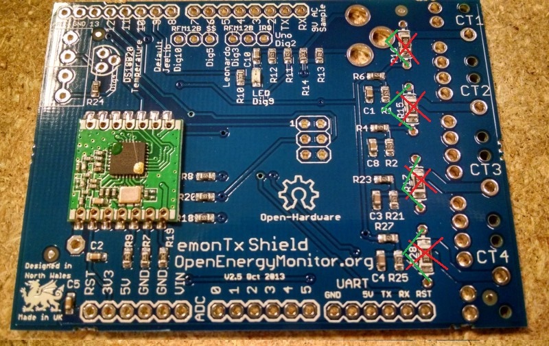
Your 30 A CTs - they have the internal burden resistor and the output is a voltage. You must remove the burden resistor on the emonTx Shield, and use a current calibration constant of 30.
The burden resistors are R15, R15, R17 & R28 and they are located immediately behind the input jack socket.
and perform the calibration actually installed a six 60.6 turn over 30?
Another problem I found a transformer 9V AC shows Out of 10.7 volts is good to calibrave calculated voltage ?:
Yes, those are the resistors. You only need remove the ones associated with the CT inputs where you use the 30 A CT.
The calibration for a voltage-output CT is different - read the calibration page again.
The calibration for voltage should use the actual no-load voltage from your adapter at its rated input voltage, therefore if 10.7 V is the voltage out when the electricity supply is 230 V and the rated input voltage of your adapter is also 230 V, that is correct. But you will still need to adjust the calibration factor so that it reads the correct mains supply voltage because both the divider resistors and the Arduino’s voltage reference might not be accurate.
The cages understood what to do, as well as voltage transformers. In the morning I’ll try to remake according to your description and try devices satisfies the appropriate precise currents. Sorry if I write incomprehensible English.
If your Shield reads the same voltage as a multimeter across your mains supply, and
if your Shield reads the same current as a multimeter connected in series with your load, then all is well.
I have just noticed this
Why the x 1.2 ? - you already have that with the 10.7, because that is the voltage you measured.
Correction calculation 1.2x9v Thank you for your observation.
okay! finally realized the calibration. The accuracy of + - 3% approximately.
Just do not understand why one phase of the 3 shows a negative value. when there is no load shows -40W difference. CT was trying to flip the still the same. before installation to check the phase sequence, according to this and combine.
What sketch are you using? Unless it has “3-phase” or similar in the name, all our sketches are for a single phase UK supply. If you are trying to measure a 3-phase supply, you must download and use the 3-phase sketch.
Calibration to work with version 2 of SHIELD and CT`s 30A.
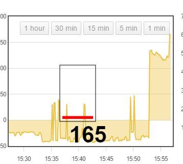
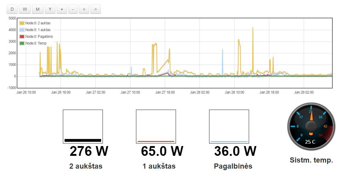
1 and 3 phase works well. Phase 2 indicate negative values appear briefly and positive as in the picture.
I thought at the beginning that will be added to the sketch values (* -1), but the value of the flip
That sketch was written for a single phase supply. As far as I know, nobody has written, nor converted, the 3-phase sketch for the emonESP. It should not be very difficult to do that. I cannot do it as I do not have an ESP to test with.
A quick solution, if it is acceptable to have apparent power instead of real power, will be to change ct1.realPower etc
to ct1.apparentPower etc
everywhere.
Hello, finally phase measured accurately without negative values.
The problem was due to a negative value ct1.realPower.
Thank you for the help of Robert Wall, helped a lot
Another problem. here touches emoncms.org can not find how to Reset a database does not delete the feeds. because many false calibration data to be saved
The sketch you are using will never read real power correctly. To read real power correctly, you should be using the 3-phase sketch.
The power that you read on the two phases that are not the one with the a.c. adapter on will be 50% of the true value with a purely resistive load, because of the phase angle between current and voltage.
I’ll try and point you in right direction but it’s not a well trodden path I’m afraid. In fact since you are using emoncms.org I can not think of any way it can be done other than delete and replace.
For info see the Deleting old data and How to limit data size threads, but these apply to self hosted emoncms instances that you can access the raw data file on.
How many feeds are we talking of? and how many inputs do you have?
Can you post a screenshot of your inputs page so I can see the number of inputs and the complexity of the processing from the coloured tags?
Or you could write a reference 3-phase sketch by my existing equipment. I really these are the distinguishing makeover to connect with ESP8266. Perhaps only this sketch?