I’m measuring my immersion usage with an Edimax smart plug right now. But I have an iboost which is technically taking some power, albeit around 1.5W by my reckoning. But also, the Edimax isn’t that accurate I’m sure.
I need to lengthen the cable that goes from my iboost to the immersion really, because it’s very tight and goes right under the hot pipe coming out of the boiler at the top.
So I was thinking of killing 2 birds with one stone and putting the current wire into a junction box, and lengthening by having a new cable coming off that. Benefit being I can throw a CT in there to measure as well.
But… The way these iboost devices work is of course to modulate the output. So am I right in thinking a CT is going to be very confused by that? Rather I’d need to be measuring very very often to pick it up?
I’m sad to say I’ve forgotten all my electrical theory I learned at uni, so looking for some confirmation from the pros here!
Yes, ideally you need a continuous sampling firmware. one of the “diverter” sketches by MartinR or Robin Emley would be your best bet until @Robert.Wall is happy with the emonCM continuous sampling library, which fingers crossed, may not be too far away.
The advantage of using one of the diverter sketches is if there is anything not absorbed by the iBoost you can divert it else where.
I tried (early models) of the Immersun and the iBoost, before settling for the Wattson (before I was involved with OEM) and I now have a “MartinR’s PLL” based monitor/diverter that mops up what the Wattson misses and continues to divert once the DHW is at temp.
Yeh, I wish I’d got into OEM before I got my solar PV installed. The iBoost came with that. I managed to wangle it for “free”. Of course, I could have wangled a discount on the installation cost I’m sure. But I liked the sound of the iBoost, and to be fair, haven’t had the boiler on since getting the solar installed and we’re only 2.56kWp. So I’m pretty happy.
Anyway, yes, I might look into these custom diverter approaches in the future. Especially if I end up buying a Leaf (fairly likely) and then can divert to that as well.
Looking at the IBoost+ web pages, it seems to imply that it uses either phase angle control of a triac, or a high frequency chopper (similar to a “Class D” audio amplifier). It’s clearly stated that it does not use burst fire mode.
That being the case, the standard “discrete sample” sketch should give you reasonable accuracy, but it might be safer to use Martin’s PLL sketch or Robin’s, without using the diverter. It’s only when used with a burst fire diverter that the discrete sample sketch gets confused.
If you do decide to divert on top of the iBoost, then you need to note that they allow a safety margin (which neither Robin nor Martin found necessary), so it might well be necessary to tweak the algorithm so that the two devices sequenced themselves correctly.
OK I’m back on this. Mainly because my way of monitoring my diverted usage seems to be dying somewhat. I’ll explain…
I had an Edimax Smartplug plugged into a socket, and my Solar iBoost plugged into that. I’ve been a bit sceptical of my immersion plugged into a 13A socket like that, but it’s how the house came, and I had a sparky check it over when he changed my consumer unit a month or so ago.
However, today I was having a look at the iBoost and I pressed down on the plug and, well, things went weird. The iBoost flicked off and on. And the shower pumps decided to give a little burst. The shower pumps are spurred off the immersion 13A socket.
I have decomssioned the Edimax Smartplug because without that, the ghost pumps and iBoost flicking off and on doesn’t happen when I press down on the plug. I also noticed that the connectors on the 13A socket that connects the iBoost are blackened a little. Presumably from years of use.
So I really want to get this sorted out.
Any thoughts on how this should actually be wired? I thought that I could do something DIY where I get rid of the Edimax, and then add a junction box between the iBoost output and the immersion heater, and stick a CT in there to measure current.
Or should I get a sparky in and rewire this completely? I really want the measurement of how much my immersion is used (as you’ll all know from my work on the MySolar + Divert app!).
Thoughts? Feel free to tell me to get someone in to sort it properly - I’ll definitely do that if it’s more than I am allowed to do as a DIYer.
According to building regs as I understand them, you’re allowed to replace like for like except in a bathroom, where everything must be done by a electrician registered with one of the trade organisations (and not even by a registered with the Engineering Council Chartered Electrical Engineer - go figure!).
It sounds very much to me as if the 13 A socket has got warm and the springs have annealed, thus weakening the spring pressure on the contacts and hastening the process. The worry is the first few centimetres of insulation on the ring main cables might have become brittle due to the heat, and that would really need professional attention. The reason for one plug doing it and one plug not is probably down to manufacturing tolerances on the plugs, and the reason for it happening in the first place might well be the additional weight of the stacked plugs.
Personally, I’d prefer the immersion to be on it’s own breaker in my consumer unit, or failing that, on a switched fused outlet, and have everything hard wired without plugs.
To add a CT neatly and safely, you could wire through a plastic box with the cable split inside to give you a loop for the CT to sit on.
Yeh I was thinking about the CT in a box. I wanted to extend my cable going from the iboost to the immersion anyway. I was thinking of using a junction box and extend and have exposed live/neutral there for the CT. But maybe I’ll just get a brand new wire which is long enough and do the CT in a box idea.
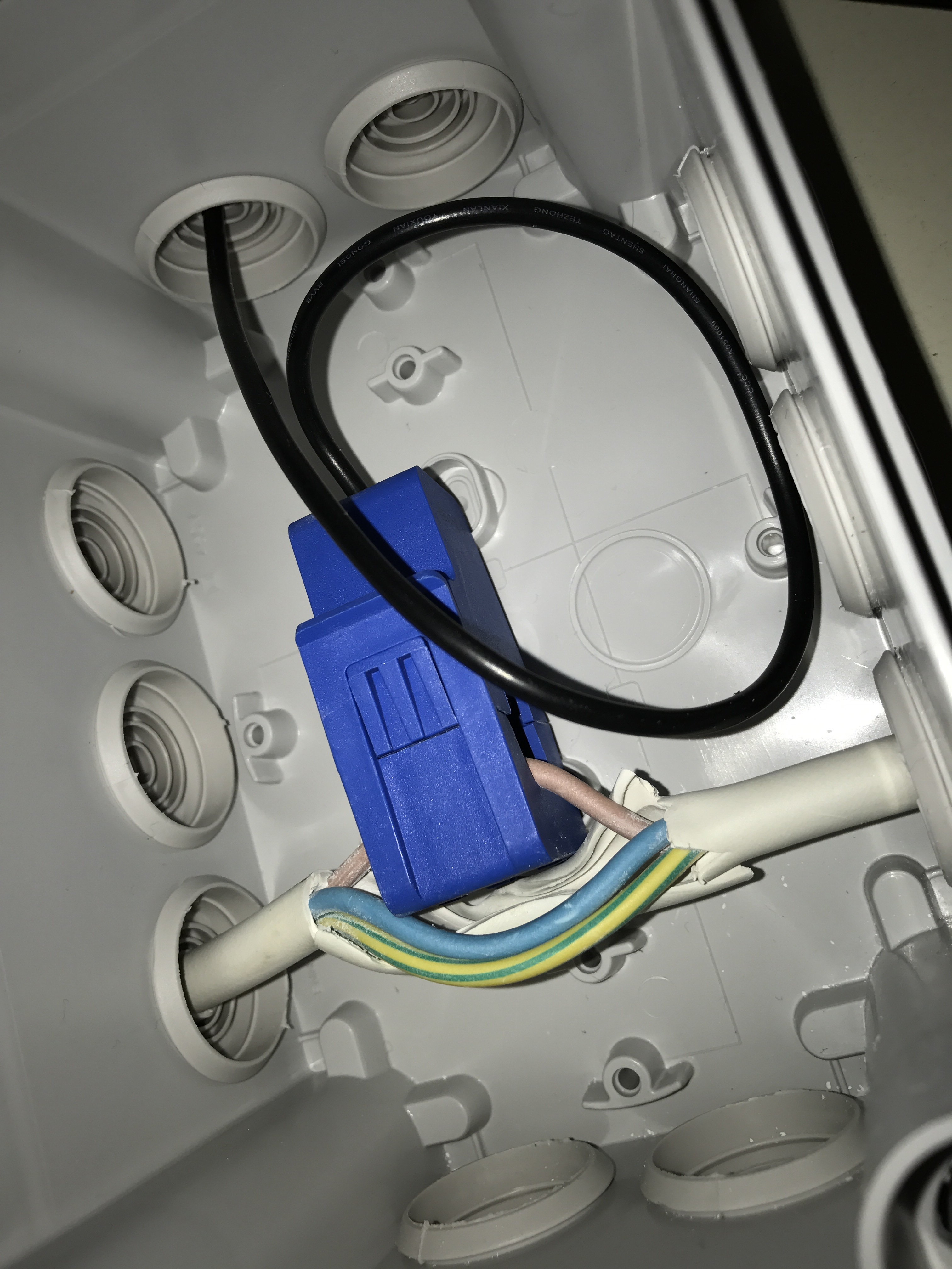
I’ve got things wired up muuuuch better now. I have a flex going from my iBoost to my immersion, which goes through a box where the insulation is peeled back just enough to get a CT around the neutral wire inside.
But the problem is, it’s not reading anything sane. I get just 10W when measured on my emonTx, which is the same as when it’s dangling free. I’ve checked that the CT and emonTx are working fine by going to my incoming main (where my emonPi is) and checking it picks up the same as the emonPi there. It does.
So… any thoughts on what I can do to trouble shoot this. I’m really confused now!
For reference, I’ve been testing by putting my iBoost in “boost” mode which just turns on the immersion full whack. I can see from my main monitoring that the power usage for the house jumps up 3kW, but on my emonTx I still see 10W.
Check the immersion wiring at both ends. Is there a switch to bypass the iBoost, and is it double-pole or switching only the line? You might have two parallel neutrals, and one is stealing all the current. Or if you have a neutral-earth fault (and no RCD protection), that too would explain it. As would the wrong wire colours (i.e. it isn’t the neutral at all).
An easy way to check would be to disconnect that neutral, but you must treat it as a LIVE wire. If the immersion still works, you have a parallel current path somewhere.
I’ve got RCD protection on the immersion circuit at the CU. I believe that answers the question that could be answered by doing the disconnect neutral test right? As the RCD is not tripping.
Wrong wire colours - I checked the connections on immersion end and iBoost end and everything is as it should be.
As for a switch to bypass the iBoost - no, it’s not that. I have a single flex coming from the iBoost to the immersion. Then on the iBoost there’s a manual boost button which is meant to turn the immersion on to max irregardless of how much excess solar there is.
Go for disconnecting the neutral. If if doesn’t draw current, it proves that the disconnected wire is carrying current, so that leaves an even bigger mystery - why isn’t the CT picking up that current?
Ok. Taking away neutral the immersion doesn’t work. Well, the iBoost displays “Water tank hot” which means it’s trying to supply current to the immersion but it can’t, and is assuming the immersion stat is saying nope.
Just because I can, I’ve put the CT around line and same problem. I mean that’s of course what I’d hope but anyway I did it!
That showed that the wire was/is carrying current, so now we’ve ruled out all the sensible causes, we’ve got to look for the very silly one.
Are you rebooting your emonTx each time you unplug the CT?
Remember that the standard sketch checks for the presence of the CTs at startup, and if one’s not there, it’s locked out permanently.
Of course, the phase angle is close to 90° when the conduction angle (hence the power) of a phase-angle controlled thyristor/triac is very small, but that’s not the case here.