Hi Everyone, I’m hoping I can test a few assumptions with you about why what I’m trying to do isn’t currently working! I have tried to read the various FAQs and try the obvious solutions (aside from one because it involves buying something, which I’ll mention later) in advance of posting this, which I’m now doing basically out of my brain having mostly given up.
I have an existing grid / solar monitoring system using an emonPi that’s been working flawlessly for a while. I also have a solar diverter which presents no surprises and also reads via a wireless clamp meter in the main meter box next to the emonPi.
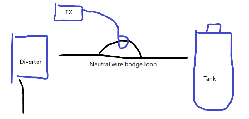
As someone that enjoys my nerd stats, I’m trying to fix the issue around not being able to split out the diverted use and the ‘everything else’ use, so I have installed an emonTx next to the diverter itself, and have set it up according to the following extremely professional diagram:
The CT is clipped onto the (safely secured!) separated out neutral wire and I’ve tried it in various different inputs, but I’m getting a situation very similar to the FAQs where the max reported figure is in single digits (typically 7) and not the up to 2.3kw I would expect. The one thing I haven’t tried is whether the CT I’m using (the blue default one) is just too big for the smaller-grade wire in use here? Is it worth me waiting for the smaller one on the store to be in stock, or would someone be able to recommend a suitable alternative? Alternatively, am I likely to be missing something completely?
Thanks.
The likeliest I think, a broken connection. What resistance do you measure tip - sleeve on the c.t’s plug? It should be around 100 Ω.
Second, what make/model is the diverter you’re using?
Because one make - I forget which - feeds the immersion heater with d.c. Transformers don’t work on d.c. Even so, I’d have expected the ripple to read more than 7 W.
If yours is one of those (i.e. not Robin’s Mk2PVRouter), move the c.t. to the supply side of the diverter rather than the load side.
Just in case you have a neutral-earth fault in the immersion heater, have you tried it on the Line conductor instead? (This was almost not worth typing - if you have whole-house RCD protection, that would have tripped on a neutral-earth fault.)
Forget that - the SCT-013-000 will read down to well below 100 W, albeit with not the sort of accuracy to be proud of.
Thanks for the reply, it’s very much appreciated. I don’t have a way of actually measuring the resistance at the moment but I could attempt to swap one of the working CTs in the rest of the system and seeing whether I have more luck with that in the interim. I’ll give that a go tomorrow and see how it goes. I have indeed tried on line rather than neutral previously and it’s made no difference.
The diverter is one of these: Solar iBoost+ - Marlec. I have to admit I’d not considered measuring the supply side for some reason, but I might have to give that a go. Back to Screwfix for some more cable (and possibly a multimeter…) I guess 
I don’t recognise that diverter as being the one that definitely runs the immersion element on d.c., but there’s nothing to indicate whether it does or it doesn’t.
As you’ve tried it on the Line conductor, the likeliest is the c.t. itself is faulty. But without swapping it or testing it, you can’t tell.
£7.50 multimeter in hand I’ve just tested and I’m getting around 105 Ω from the CT plug, so it looks like it’s not that. I also confirmed by swapping around and the known-good CT doesn’t work there either. When I get half an hour spare I’ll swap to measuring the supply side and see where that gets me. Thanks again for the help.
This is weird. Your diverter must be spitting out relatively clean d.c. - that’s going to be proven when you transfer the “bad” c.t to the supply side and it works - hopefully.
It shouldn’t make any difference to the heater to run it on d.c., but the thermostat won’t be too happy - it’s a lot more demanding on the contacts than switching a.c.
If it is driving the heater on d.c., and if you’re in serious geek mode, it might be a thought to look at shutting down the output when the 'stat hits the temperature (or better, a sensor says it’s almost at temperature) rather than switching d.c. with a pair of contacts that were never designed for that.
Just to update, it appears this absolutely was the issue and having switched the CT to the supply side I’m now getting accurate figures. I’d never in a million years have guessed it wouldn’t be outputting AC and would have been off down every rabbit hole imaginable, so hugely grateful for the guidance!
1 Like
To be honest, I wondered whether that really could be the problem, then I thought better of it, but then there was very little left that it could be, especially when you wrote that the c.t. itself was good.
I’m going to rename this thread because the make of diverter needs to be mentioned in case somebody else falls into the same trap.
I suspect the reason is the need for filtering on the output side. If you think of what happens when you switch a relay with a transistor, you need a flywheel diode to circulate and dissipate the energy stored in the inductance when you turn the transistor off. If you’re chopping up a.c. and feeding that through a filter, necessarily inductive, you have the same problem - except that you can’t use a flywheel diode. You have to do what another well-known make does and use an active switch that works in exactly the opposite sense to the switch that does the chopping, and if the timing goes wrong, you have a dead short across the supply.
A final cautionary word - keep an eye on the state of the contacts in the thermostat, if possible. Switching d.c. - especially if there is a filter in the output - might lead to them burning somewhat faster than would otherwise be the case.