There is increasing interest in using IotaWatt in a three phase environment. Although I live in a place where residential three-phase is virtually non-existant, I have tried to make the device adaptable to a variety of potential adaptations for that environment. Here in the USA, that would also have wide application in commercial environments.
Except for a couple of users with homemade IotaWatt, everything to date has been academic since I haven’t had access or time to do measurement and experimentation with polyphase, except for split-phase residential which I’ve used to tstsome of the underlying polyphase capabilities.
IotaWatt is capable of supporting multiple VTs for absolute voltage reference on each phase, or it can numerically shift a single reference to approximate power on all phases. There is support for each of these approaches in the existing offering, and there is potential to enhance the configuration utility to make it easier to sort out the various options and phases.
This thread is the place to ask questions about what exists and what is possible, as well as to contribute experiences.
Single phase and three phase are common in Australia but my father has two phase - one phase for the house and another for the shed. I suppose it is only two of the three phases. Anyway, just raising it as another configuration. It’ll probably end up with an IotaWatt.
Part of the problem with three phase is testing, since not many of use have access to three phase. Thanks to @jeremypoulter for sending me this blog post on how to simulate 3-phase AC for testing:
I’ve been looking into a different approach. A common industrial method is to use a three phase motor as a rotary converter. I’ve been looking at getting a small (1/4 - 1/2 hp) surplus motor, or a little there [sic] phase motor from china :
you could just use a car alternator and take out rectify diode or just 3 leads connected to the field to produce your 3 phase then just adjust your rpm to get the HZ you would like - it would be cheap method of producing 3 phase as you can get a scrap car alternator for almost nothing
Another good idea. What I like about this is that the test rig could potentially be low voltage, so decent current levels can be produced without the need to do multiple primary turns or burn a lot of power. Sensing the voltage on each leg could be tricky.
Driving the alternator with a single phase ac motor and the appropriate ratio drive belt would get it in the the working range.
i use to build 3 phase wind gens as a hobby – just remember to leaves a a small resistant load on of some form. as the the open voltage can be very very high- or take the charge controller out of the alternator leaving in only the bridge rectifier connected to say a 48 volt battery- since the alternators are generally built for 12 volt maybe at your rated HZ it might only charge at 1/4 amp or less at 48 volt … then just draw your 3phase before the bridge rectifier . .- the reason I say use a battery as the resistant load as soon as the voltage drops below the battery voltage it does not have any effect on the alternator output… but just a thought
For my 3 phase monitor I took the approach that it’s simply three single phase monitors in the one box. The only coupling between them is a common neutral. That’s true for the 4-wire “Y” configuration that’s common around these parts; I have trouble getting my head around some of the other 3 phase configurations in use around the world. That meant I could do all my testing and calibration in a single phase environment. When I eventually installed one in a real 3 phase environment, it worked fine.
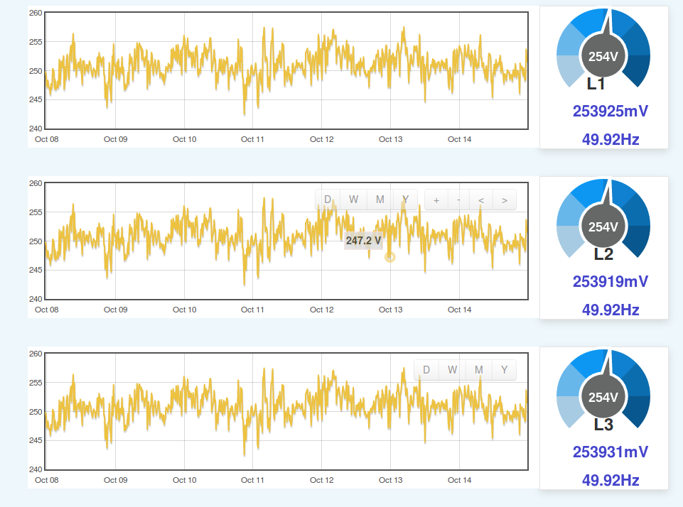
I only have a single phase house so I simply run that single phase to each of “phases” on my 3 phase monitor (Clamp meter positioning - #26 by dBC). For kicks I set up some dashboards as if I did have three phases and see extremely good phase voltage balances as a result (all three voltmeters are aimed at exactly the same signal):
I know people claim to have had joy with 3 phase sketches that fabricate the other two voltage signals from the one that is being measured, but in my limited experience (Aus and NZ) that’s nowhere near accurate enough due to the large voltage imbalances between the LV phases. I can see the attraction of that approach however, given OEM’s absolute requirement of VTs for safety and isolation. Getting three wall-warts all plugged into outlets on three different phases and their outputs all run to the monitor can be very problematic. Here in Aus it’s not uncommon to have a second phase added for a dedicated purpose like air-conditioning, or the shed, so it can be close to impossible.
I’ve never been overly convinced by “long term agreement with my revenue meter” observations. That just means your errors are averaging out to zero, but any single observation like “how much power is X using right now?” could be way out.
All of these problems go away if you can get access to all three voltage signals in the one location and the best place to do that is near the meter and main breakers, but the safety issues there mean it’s outside the reach of the home hobbyist. You could potentially get a sparkie in to install a 3 phase outlet with associated 3 phase breaker etc, and then wire your 3 VTs to a 3 phase plug but that’s going to cost money. I know of quite a few 3 phase homes in Aus and NZ but none of them have a 3 phase outlet. At least here, 3 phase appliances are unheard of (except maybe for arc-welders). The houses have 3 phases (or sometimes just 2 of the 3 as flywire pointed out above) to spread the load.
@dBC, thanks for that. Good explanation of the practical aspects of dealing with three phase measurement down-under.
I agree that having individual reference for each phase should be the gold standard, and can also see how that might not be practical. So the question I have is How accurate a story can be told with a single reference. Is that something that would be useful on some level,
As I understand it, there is an Emontx sketch that numerically phase shifts a single VTs to give some estimate of total three phase power. There’s also a methodology of using three TX or two TX and a PI to do the three vt method.
I believe the iotawatt can support both methods, but I don’t have any test sites yet to gather data. I’d like to compare the numerical phase shift method to the three VTs standard and measure the difference. Both can be setup on a single iotawatt. Same goes for the “two phases” service.
If the numerical method is typically within say 5%, then it might be worth developing an easy user interface to do that.
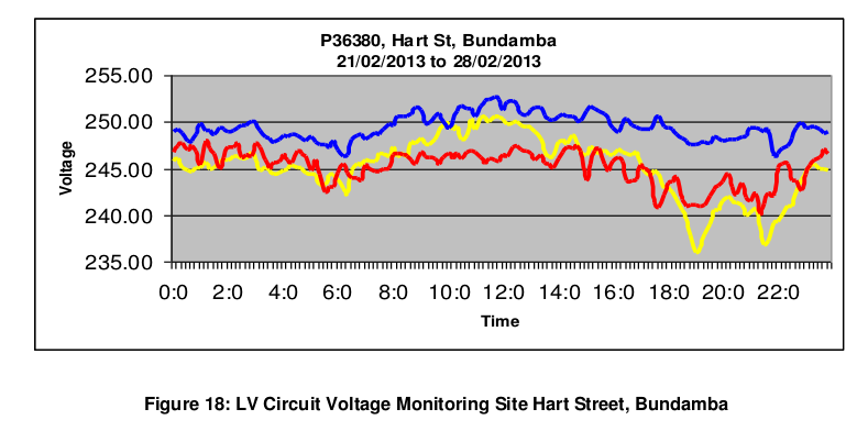
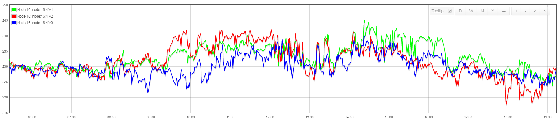
I think the voltage imbalance is probably the biggest risk to accuracy and I reckon that’ll vary enormously from location to location and throughout the day, so would be very hard to quantify without measuring it, and to measure it you need 3 voltmeters logging the data. Here’s one that our network provider published from a specific location on the network, averaged over a 1 week period:
So 2-3%. That’s actually encouraging. I see variation between the two sides of my US split phase service, yet reasonable results can be obtained using one leg. This variation is a little more, but not drastically different.
To make matters worst, I have some friendly neighbours/solarpanel installers who ignore the Belgian voltage capping and often on sunny days I manage to measure 250V and beyond on one of my phases, causing high voltage spikes and drops which shutdown one of my PV systems.
I have 2 solar invertors, one connected to the 1st phase (green) and one connected to the 2nd phase (red). The panels are located on 2 sides of the house, facing east and west. Green is east, red = west.
All these values are measured on a seperate voltage transformer for each phase. I have 3 outlets installed near my electricity cabinet, one for each phase and thus connecting one adapter to one TX. I use some of the openenergy community i2c magic to couple the 3+1 TX boards together and send the data to my local emoncms installation. I really like your solution with the ESP; I was in the process of building a 3 x 12 CT board with an arduino due, but it got on the bench due to lack of time and I feel like it might be replaced by this nice piece of hardware.
But as there is now an own three phase thread I will continue here:
I played around with this and tried to set up the IotaWatt for three phase systems. But I did not succeed with this. Btw there is a simple method to test a three phase setup with only one phase. Set all three CTs around the single phase. Now the first CT should of course measure the correct power, the second and third will show exactly the half of that and the value is negative and the power factor is also -0.5 if you have a pure resistive load on the single phase like a kettle causes. The reason is that cos(120) and cos(240) are both -0.5.
Actually I wanted to post some screenshots of what I tried, but I can’t connect to the IotaWatt at the moment. The reason is that I moved the IotaWatt to another location for the three phase test. At the new location the IotaWatt opened the access point again (which was of course what I suspected) but it was not possible to connect. I tried a half an hour with a lot of hard resets till I eventually succeeded. Back at home I can now reproduce the problem with a mac and a windows laptop and I did not succeed till now.
Sounds like you have everything already in place to install an IotaWatt. The hurdle seems to be availability of three voltage references which you have already in place. I’m going to send OEM some adapters to connect a standard VT to an IoTaWatt 3.5mm input. It’s a simple circuit with one resistor. If you decide to order an IotaWatt, specify that you need two of these adapters. When they get them, they will forward to you.
Keep me posted on your progress. We are very interested in getting some user experience with the various techniques available in the IotaWatt.
This method did occur to me awhile back, but not having any real-world experience with three-phase, it just seems too simple. I have to respect that the resident three-phase guy in these parts has never suggested it, and went to great lengths to do a phase shifted approach of the one VT. I had it in the back of my mind to research it. I have confidence it would be good for unity PF, but would have to do some math to determine if it would hold true as the PF drops.
Id be interested in trying to get the phase shifted CT method working and then compare the output to the doubling method. First on a unity load, then on something with a low power factor.
WiFi range can be an issue. I’ve got one in an outbuilding measuring my meter feed. It doesn’t connect when it rains. When the rain stops, it uploads the backlog. I do have a couple of little plug in WiFi relays that I’ve used in the past. They work fine and solve the range problem.
I did not change the name and the password “IotaWatt” is saved in the keychain of my OS, so typing in the wrong password can actually not be the issue. But after a lot of resets I managed to establish a connection and finally changed the WiFi settings, so it’s working again.
Does changing WiFi settings work for you without issues? Maybe there is something wrong with only my IotaWatt?
 :
: