That might be the case regarding wear levelling but have you considered basic SD card corruption?
I know SD cards offer a very low cost storage solution but certainly my experience is that it’s not a system that can be relied upon.
Have you considered SPIFFS?
Have you considered an internet only solution i.e. internet is inherently reliable and for the odd occasion it’s down simply forgo energy monitoring. For me I would be more concerned about the internet being down than knowing how much energy I had consumed, and associated cost, during the outage.
can you point us to some data that demonstrates the probability and/or severity of this? SDcards have become ubiquitous. Anecdotally my experience is just the opposite of yours - it seems to be very reliable in this application and everywhere I use them. Virtually all of the SDcard problems I’ve encountered were of my own doing in misusing the FAT file system layer that is between the code and the physical card.
My understanding is that SPIFFS is the same technology as the SD card. Also, it wouldn’t hold a day’s worth of data.
I’m not sure what problem that solves in the context of these questions. IotaWatt does log to the internet, in fact it currently supports two different time series database servers. (Emoncms and influxDB). Support will also be added soon for MQTT which will be a generic bridge to a variety of other data servers. What would be the advantage of removing the local SDcard storage capability?
I guess I don’t know what aspect of the internet makes it inherently reliable. In the context of this question, the internet is: the local WiFi router; the ISP; the internet backbone; The server’s ISP; the server itself; and the server application that I connect to; That’s a lot of moving parts. IMO an SPI link to a local SDcard looks pretty good.
I haven’t had any IotaWatt installations report SDcard failure. On the other hand, there are hundreds of cases where one of those links (usually the local router) failed for some length of time and the data was subsequently automatically batch uploaded from - you guessed it - the SDcard.
thanks for your constant and professional work at the IoTaWatt device. It’s great what you achieved with only the ESP. I’m currently testing it, here are some first impressions:
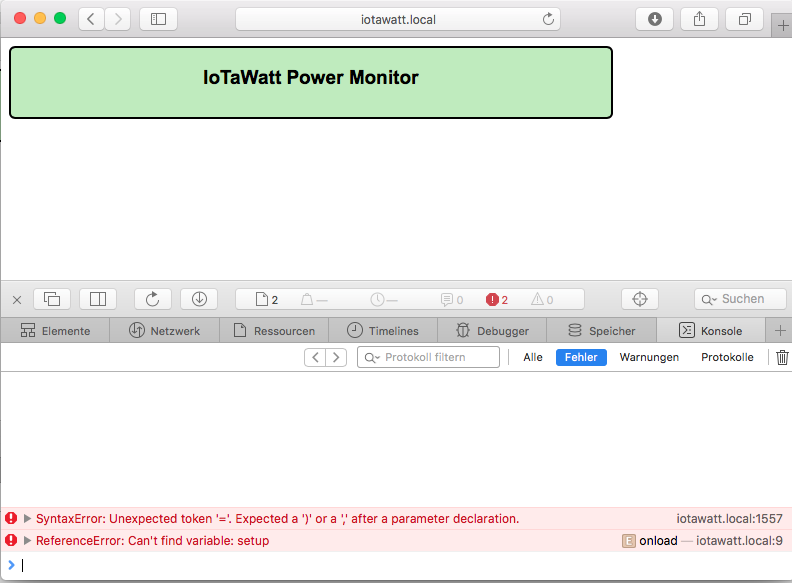
it’s not working with Safari browser, here is a screenshot:
Elias,
Can you give me some context on this post? Where did you get your IotaWatt and what firmware are you running?
I wasn’t aware of that Safari incompatibility. It has always run fine on my Ipad Safari browser. I’ll have to look into it. Offhand I believe that is the only place I use a default parameter value.
I elected to run graph, the message log, and the editor as a new page rather than mess with frames. Browser back button does the job.
You can’t. It’s only available on the status screen. Keeping that stuff in the datalog is a huge increase in storage requirement and I’ve had very little interest in that data historically.
Best part is that with low tolerance components, it’s usually pretty good without calibration when using a standard VT.
It should work right now. There are two ways to do it:
You can add two more VTs to get voltage and phase reference for each leg. I plan to make some adapters to allow connecting a standard issue VT to any of the power channels. If you want to do it yourself it involves changing the 5.5mm barrel connector to a 3.5mm stereo jack and adding a 288ohm (or the next higher available) 1/2Watt resistor in series. After that, you configure (and calibrate) the new VTs, you will have the option of specifying the VT that corresponds to each power channel. You can customize outputs to display and Emoncms to add together the various legs of a three phase device (or mains).
Another way is to just use the generic CT specification on L2 and L3 and add 120 and 240 degrees to the phase lead respectively. That probably won’t be as accurate as the three VT method, but might serve your need fine.
sure here is the context: I work with a few people in a project in germany with quite similiar goals like the openenergymonitor project. We help people to understand what energy is and how they can use it more efficiently. In order to “make the energy flow” visible we are using mostly emontx. In germany it’s common to have a three phase supply so we use the three phase firmware for that (which by the way was improved grandiosely by Robert W. in the last few weeks). We got a sample IoTaWatt with our last order for evaluation/testing purpose.
I’m on the alpha update channel, so the current version is 02_02_19.
We are involved in some scientific project, where powerfactor, current and frequency is interesting and important too. So having the opportunity to log theses values too, would improve it a lot for us. On the other hand we usally don’t need 14 channels for power.
Sounds plausible, I will have a try with that.
By the way: Are you going to publish and document the update server part as well? That would enable me to have some IotaWatt in a specific project with a customized firmware and still use the auto update feature.
Glyn hadn’t told me that he sent out any units. That said, I am happy to hear that he has. I was hesitant because it’s a lot more straightforward dealing with someone with a production unit vs the a homebrew device. Not to diminish those efforts, but the approach to problems is easier.
Yes, that is the current version.
This is a tough issue. All data logging is accomplished by reading from the log and posting to the server. That architecture makes possible the wifi/internet failure recovery and uncouples the server posting from data collection. So whatever gets sent to a server must be in the log. As I’ve been trying to get this thing under control and released, I have avoided mission creep, to the point where expanding the log file record is a backward compatibility and conversion issue as much as a technical challenge going forward. Let me process this in the background for a few days.
That concerns phase shifting L1 voltage to L2 and L3. That’s basically what the eMon three phase sketch does, if you like that, you should love this. The gold standard of course is using three VTs which is also supported.
The update server is just loading the update onto a server and downloading the file. There is a php file that you can query to find out what version is current for a patrticular update class, but then IotraWatt just downloads the file as it would any other file. So the update server is just any webserver like apache.
The update blob itself is a different matter. I build that offline in an ESP8266 device that I call my “enigma”. OTA updating is a security nightmare. IotaWatt doesn’t have enough heap to reliably use TLS for secure internet downloads, and a method of authenticating an update is needed anyway. I do that by signing the update blob with a private key that is kept in the EEPROM of my offline enigma signer. The corresponding public key is hard coded into IotaWatt. The OTA update requires that the update blob signature verifies with this public key. Most users will take comfort in this arrangement and my intention to never share the private key with anyone or even expose it to the internet.
So the issue becomes whether I want to become a CA and administrate update certifications beyond what I have already put in place, and will I also need a revocation process as well, and just how far do I want to go in reinventing the wheel?
Before I think about any of that, I’d rather explore the needs of the user base and see if they can be met with mainstream changes in the official releases. It is open, and you can do a pull request.
I wanted to find out what device you had before addressing this. Now that I know, I think the problem is that your device probably doesn’t have a battery yet. Open it up and see if there is one. It takes a CR1220 lithium coin cell. (the screws are under the rubber feet that just pull off).
Spoke an instant too soon. Everything is there and working, but I was just trying it out to be sure on my split phase US system (L2 is 180 degrees from L1). Discovered that I had limited the phase shift specification in the app to 5 degrees. It’s a two line JS change and when I did it and configured an HWCT-004 (1000 turns .5 deg lead) to generic 1000 turns 180.5 degrees lead, it worked fine.
I have another fix for another ALPHA user so I’ll put that together with removal of the phase spec limit and push 02_02_20 to ALPHA update class tonight or tomorrow.
I’m eager to get some experience with this, both to determine the accuracy and to figure out a simpler way to approach the user interface. Im thinking along the lines of specifying that the appropriate three phase (or split phase) shift should be set automatically. Iotawatt can determine the phase shift of a CT from a VT, and round that to the nearest multiple of 120 to get the base three phase reference. Maybe we can try a few different approaches, but that would make deployment pretty simple.
@overeasy: I’m also curious about this! I bought 2 extra VT’s, but i can compare them on the same device. @Simsala: you can get the powerfactor and frequency from the device via http (ip_of_iota/status?inputs=yes&outputs=yes&stats=yes"), so you could log it that way? I’m using this to display it (not logging) on my domotica Rpi-server.
It does work, just not sure how accurate it is. Not a power engineer, but there’s a good OEM Learn section about how varying loads can change the apparent phase angle. So at this point I don’t know if using one phase as a reference for the other two is viable. At best it assumes all three phases have the same voltage. But depending on the accuracy required, it may be a good choice for a lot of three-phase. At this point I just don’t know. The OEM “three-phase-sketch” attempts to do this, and @Simsala says he has a new improved version, so I guess it’s working already for some folks with the TX. If it’s not up to snuff for a particular user, the three VT solution should be. You can try it both ways. That will be a good test. You should be able to do both at the same time on a single IotaWatt.
Yea, that’s one way to do it. You’ve been reading the code. But there are some caveats:
The status display values are damped, so they are not the same as logged values.
That method will only work in real time, whereas logging that data to the SD card and posting to a configured server will save insure against data loss in the case of internet disruptions.
The data is produced, but the devil is in the details. How to add it to the log without doubling the requirement for everyone, and how to put it into the user interface without needlessly complicating it for most folks who couldn’t care less.
I have some ideas, but it needs to simmer for awhile. It involves a separate auxiliary log, possibly at a longer posting interval. Most of the internals to support the current log are implemented in a class for which another instance can be created. Stay tuned…
I was thinking the same, that would make deployment indeed a lot easier!
The battery was there, but it was a cold solder joint of one pin of the battery holder. I did solder it, it seems to be working. Now, only the first entry after reboot has no time stamp “No clock yet: SD initialized.”
Thanks for the hint, and good too know that I’m not the only one interested in these values!
Sorry about that. Not the first one I’ve had. That particular one has been a problem because the battery holder itself is a huge heatsink. I needed to crank up my iron to fix the last one. I’ve started using a higher reflow temperature in my toaster-oven, but the manufactured boards should not have that problem.
It’s normal for the first line to have no timestamp.
@overeasy: i was going through the code and was wondering what the difference between ADC_BITS 12 in IotaWatt.ino and _ADCbits = 12 in IotaInputChannel.h is? They both define the same ADC (MCP3208) i guess?
I don’t remember offhand. There’s a lot of baggage in there from the various stages of developing this. At one time, I entertained the notion of using MCP3008’s (10 bit) but when I saw the stunning increase in accuracy, I went all in on the 3208.
Right now I’m in the middle of converting the source to work with platformio. As time allows I’ll be cleaning up some of the detritus from efforts past.
What I did notice: The device name as shown by my router is still shown as “ESP-238CA3”. The emonESP is listed as “emonesp”, which is quite nice and makes it easier to find. Didn’t try it but I think it’s the hostname declaration EmonESP/src/wifi.cpp at master · openenergymonitor/EmonESP · GitHub
@overeasy: just to be clear: to measure something connected to Phase2 using a VT connected to Phase 1 i should increase the phases number in the config.txt by 120? (on a 3 phase setup).
I tried this on an input i had running, but it seems that the measurements are a bit off…(still running 2.02.15)
it says 44 W where it should be around 100. (using the vt on phase 1 and adding 120 for phase 2)
it says 3 W where it should be around 53 (using the vt on phase 1 and adding 240 for phase 3)
I restarted the iotaWatt after changing the config.