Hi,
I have recieved my 4 emonpi and 4 emonTx. i have a question if i connect them all to the server via POE switch would i able to get the reading from the devices on the software/interface end?
Thanks
Hi,
I have recieved my 4 emonpi and 4 emonTx. i have a question if i connect them all to the server via POE switch would i able to get the reading from the devices on the software/interface end?
Thanks
No. The RJ45 port on the EmonTX is not an ethernet port and the Pi by default is not POE compatible.
If you power them separately and connect an ethernet port, they should be OK. Are they all within radio range of each other?
Hi Borpin,
They all are on different chambers within a range of 3-5 meters. Yes, they are in radio range.
within radio range would i be able access them all together from the interface.
@Gwil - I think this may be an issue.
The most the EmonTXs are setup for by default are to use 2 simultaneously - the other 2 need the NodeIDs modified so you can use 4 simultaneously.
You could have just got one EmonPi and linked the 4 EmonTXs to that one EmonPi - this is still the best solution with one caveat - you may get radio interference between them (@Robert.Wall).
What is your level of technical expertise?
Thanks, I am network Engineer and working with Siemens to digital the manufacturing factory step. One of the bit is to collect all the energy usage data and analyse it. I don`t have much of expertise’s in electronics field. However, i bought these device and have already configured the software end on Linux Ubuntu.
My thoughts where that i would be able to connect them all together through a switch and connect it to the server. but as you mentioned above that cant be done
Let’s start with the basics.
The emonTx is a power measuring device that by default transmits its data on the 433 MHz ISM Radio band. Depending on the situation, those transmissions can be received up to 100 m away (so I’m told, I’ve received over 30 m with no problem, and about 10 m and through several brick walls with no problem). It requires a power supply, usually it can use the a.c. adapter that also measured the mains voltage.
The emonPi is both a power measuring device and a receiver for the radio data transmitted by the emonTx. It requires an a.c. adapter to measure the mains voltage, it also requires a 5 V d.c. supply to power it.
All emonTx’s transmit on the same radio frequency. The message is short, only about 10 ms duration repeated every 10 s or so, but it’s possible for two to transmit at the same instant: each will jam the other and neither message will get through.
Each message carries an identification - the NodeID that Brian referred to. Each emonTx must have an unique Node ID. You can only change the second emonTx’s ID by using the internal physical switch that the emonTx has, you will need a computer and FTDI programmer to change the third and fourth.
So if I understand your proposed set-up correctly, each emonPi will receive all four emonTx’s, and then it will send - either by Wi-Fi or Ethernet cable - the emonTx’s readings plus its own to your server (even though the emonPi IS a server running emonCMS - so you’ll potentially have 5 databases all with potentially the same information - one on the server and one on each emonPi).
There’s just one thing that might affect what I’ve written - what exactly do you mean by “chambers”? What is the construction material, and how will it affect radio reception, is the real question.
I think that you only really need the 4 EmonTX devices and possibly one of the EmonPis if you use the RFM route. Alternatively an EmonBase (a Pi with an RFM card) might be an alternative RFM solution. If you do use the RFM route, you will need to modify the settings on two of the EmonTXs by connecting via the UART (as Robert said).
Alternatively you can connect each EmonTX directly to your Network either with an EmonESP or an RPi Zero and send the data to your server that way.
As we don’t yet know the full details of the installation, it’s hard to know what will be the best solution. I think it’s fair to say that @Hassanwahab didn’t understand, at the time he placed the order, how the OEM equipment works, our problem is to help him get to a place where he’s got a working system.
I’ve worked with Siemens people on a steel mill, but that was a long time ago now.
I think that is probably enough info to be going on IMHO.
I read that - believe it or not. But I still sense there might be other complications.
Thanks All,
I will initially add 2 emonTx to 1 Emonpi and check the results. meanwhile, change the Node ID`s on the others.
The chambers are called Soak chambers where we test bare boards/populated circuits boards on high temperatures. and other PM2 switches and chips.
I think you all have provide enough information which would help me to run the devices and get some results.
Thanks again.
So the emonTx will in fact be external to the soak chamber.
In your emonPi, accessible through the browser interface, is a file called emonhub.conf. You need to ensure you have a specification for all four NodeID’s that you’re using, and you must not duplicate a NodeID within the file. As it comes, NodeIDs 15 & 16 are designated for the sketch that I presume is in your emonTx (16 by using the DIP switch - see the Guide for details), and you copy that section to whichever new numbers you choose - probably 17 & 18, which aren’t specified as yet.
Note there’s an error in some versions of the emonhub.conf file for nodes 15 & 16:
datacodes = L,h,h,h,h,h,L,L,L,L,h,h,h,L
should be
datacodes = L,h,h,h,h,h,l,l,l,l,h,h,h,L
(Energy values “E” are signed int32_t variables - datacode “L” treats them as unsigned. It shouldn’t affect you as you’re not exporting energy from those cabinets.)
Thanks Robert. Noted
Hi Robert/Brain,
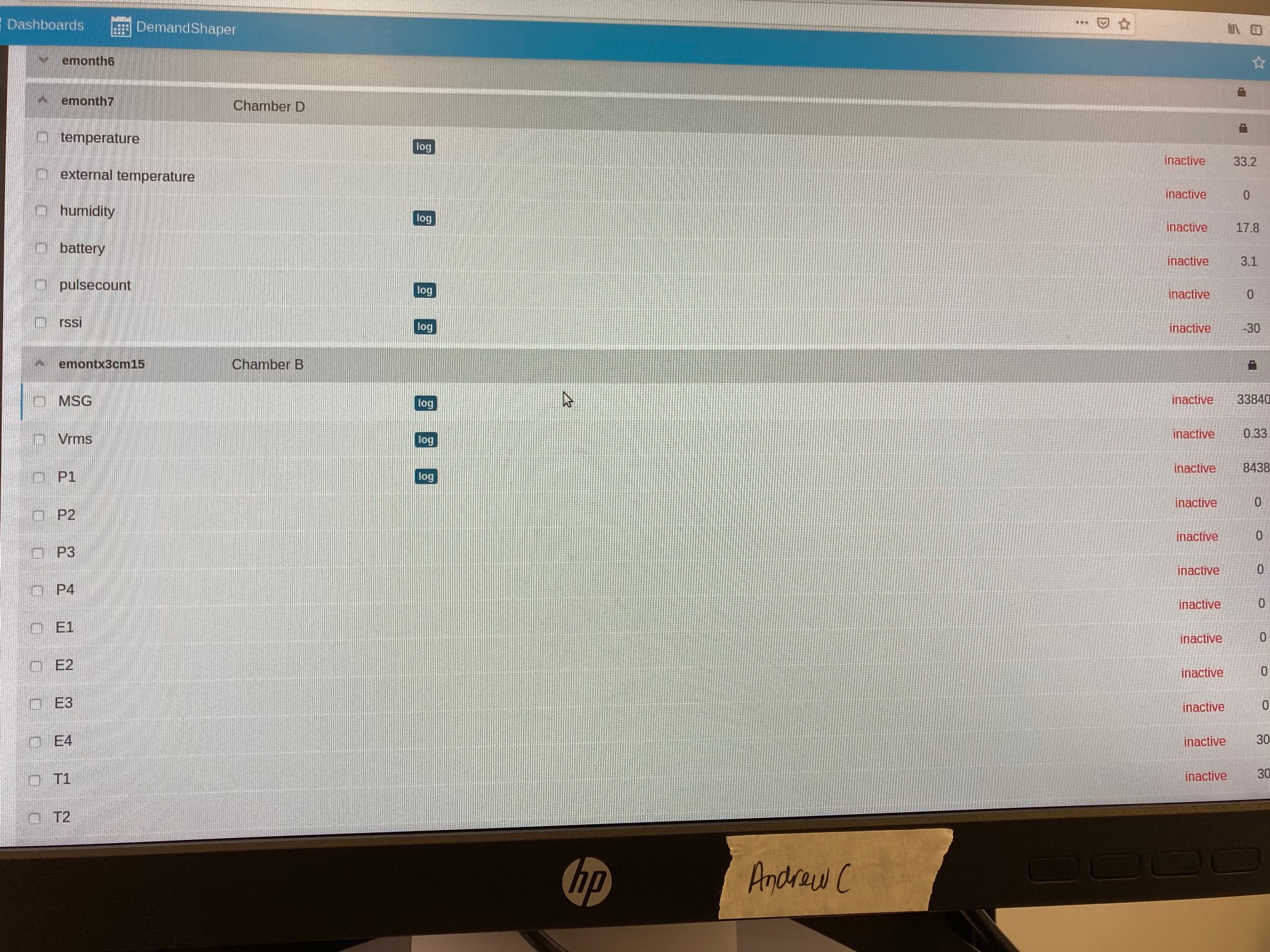
I have done as you people advised above. I am receiving the intial reading but it says inactive next to it. please see in the atatched screen shot as advise.
Thanks
and advise*
“Inactive” means that data has not been received for some time - I don’t know the exact duration.
Originally you were going to have 4 emonTx’s sending to 4 emonPi’s sending to a server somewhere. Is that still the case, or have you rationalised it, and where does that picture relate to?
And if possible, please post a screen capture, it’s much easier to read than a photograph.
Do you have 4 EmonTH as well by any chance?
[edit]
Is the time set correctly on the EmonPi?
Admin page under Server
Next will be a portion of the Emoncms Logs and then the emonhub log.
Hi Brain,
i connected two EmonTX and two EmonTH to Emonpi. I connected to Emonpi wirelessly via web interface created an account and created input feeds. i also changed the DIP switch configurations for one EmonTX and EmonTH respectively.
The time on Emonpi is not up-to-date. and i am getting inactive readings.
I am using the emonpi without any internet access.
Thanks
Ok, that is the issue.
Without an internet connection, the time can never be set on the EmonPi.
You either need to fit an RTC (not easy on the EmonPi) or use an internal NTP server.
[edit]
I said never, but what I meant was that the only means of setting the time is manually after every reboot and it will drift.
Actually it’s easier to install an RTC on an emonPi than to a RPi with an RFM2Pi fitted as the emonPi add-on board has a dedicated footprint “Aux gpio” for a RTC to be fitted. As long as you can solder a header to the board, your good to go after a little bit of config. It’s in the Wiki.
https://wiki.openenergymonitor.org/index.php/EmonPi#Adding_a_Real_Time_Clock_.28RTC.29
IIRC it might make it a bit snug in the case, but I believe it does fit ok. Add a bit of insulation tape or cellophane if the RTC chosen has soldering or components that sit proud and close to the metal case.