I’m using the circuit from the Learn/Current Only Arduino Energy monitoring page, but using an ESP8266 board
I have an SCT013-030 so I’m not including the burden resistor (its builtin to the SCT013-030)
I am driving a voltage divider from the 5V Vcc on the board with the 10uf capacitor and I have the 10K and 2.5K resistors to bring the reference voltage to 1v
I initilize the emon with
emon1.current(A0, 30.1); // Current: input pin, calibration.
and calculate IRMS with a 20 second delay in between readings
double current = emon1.calcIrms(1480); // Calculate Irms only
I expected to see low readings (0.02, 0.06 etc) when the washer is off, and higher readins (0.5, 0.8 etc.) when the washer is filling.
I get the expected readings when the machine is filling, but I get various readings when the machine is off.
Sometimes the readings are low as I thought they would be; other times they are higher - identical to what I see when its filling.
I monitored and logged data all day (without doing laundry) and it will read low (0.02, 0.04) for a few hours and then jump up to 0.6 0.8 0.5 even when the washer is not in use, then return to the low readings. This is making it impossible to tell when the washer actually starts.
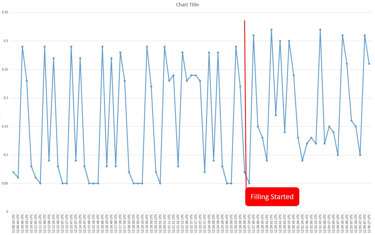
Any ideas why I am seeing the higher reading when idle? Or is this expected behavior? I was going to take a series of readings and average this out in software, but that does not seem feasible (see the attached graphic)
I am powering the ESP8266 using the USB cable and an USB power block.
The block is plugged into the top half of the outlet and the washer is plugged into the lower half of the outlet.
This outlet is on a dedicated circuit breaker for the washer.
I tried using a couple different USB power blocks thinking maybe the first was noisy or having issues and not generating the 5V consistently but I’m getting the same results from different blocks.
A graph of the readings at idle and when the fill cycle was started (the red line indicate the point that the washer was started.)
What is the quiescent voltage on the analogue input pin? It should be 0.5 V, if the input range of the ADC is 0 - 1 V. See Learn → Electricity monitoring → CT sensors → Interface with an Arduino
To translate that waveform diagram to your ESP, the “Arduino 5 V d.c.” actually means your ESP maximum voltage input, which I think is 1 V. Therefore your resistors need to make “midpoint” 0.5 V so that the voltage from your c.t. can swing from 0.5 V down to 0 V on the negative peaks and up to 1.0 V on the positive peaks.
When you’ve done that, you might find that your maximum current is half that you expect. You can easily add a second external burden resistor across the C.T. connections to bring it down.
(The c.t. will be quite happy with that, but you’ll need to recalculate the calibration. I think the internal burden is 60 or 62 Ω, but I’m open to correction.)
Also, from memory, the ADC is very slow compared to the one in the Atmel328P, so you will need to check the speed and adjust your sketch to match (i.e., 1480 samples may be way too many - you want about 200 - 500 ms worth, and ideally as close as you can get to a whole number of cycles).
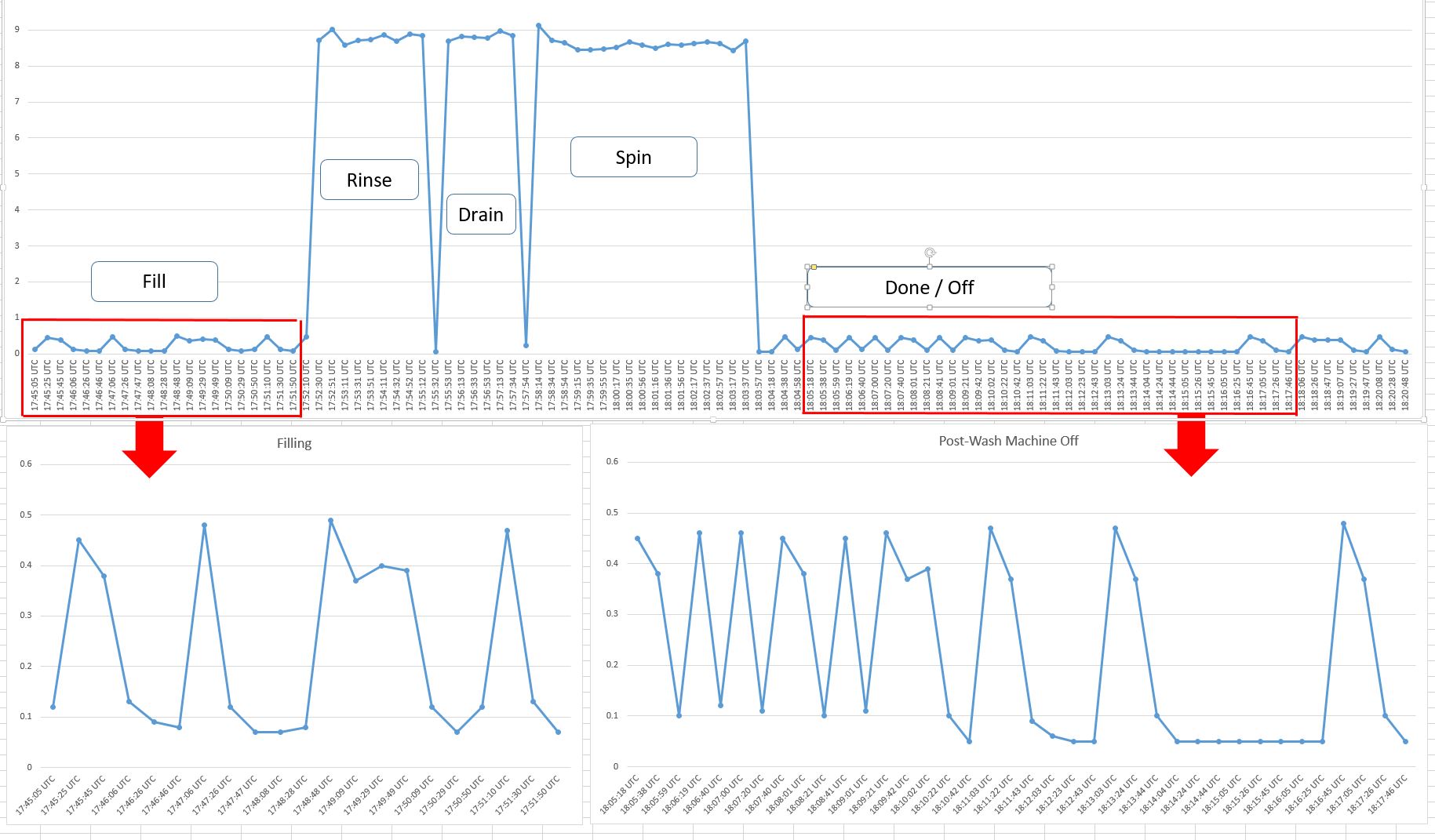
Robert - thank you for responding so quickly. I’m using the NodeMCU -12E version of the ESP. This one can handle 3.3v input on the ADC pin; I was originally assuming 1.6 as a midpoint but using 1v to have some safety in case of spikes etc… I had read the interfacing with Arduino page, but I understand it much better now, your examples helped. To be sure though I changed resistors to get to 0.5v from the divider and ran another test. I’m still getting the same pattern of readings where the values for “off” and the fill stage are the same (see image). For what I am trying to do right now, its not as critical to have the exact current (I do want that later), I mainly
want to sense changes in state from off, filling, running, off etc.
Do you have any idea where I can find info to help me calibrate the sample size? Looking at the emon library I noticed there is code to help detect the vcc of the device (3.3v vs 5v). How important is that for getting the correct current calibration?
Robert Wall wrote:
You can time the code like this:
unsigned long timethen = millis();
double Irms = emon1.calcIrms(1172);  // Calculate Irms only
Serial.print("Time ");Serial.print(millis() - timethen);Serial.print(" ");

This gives you the time to read (in this case) 1172 samples. The time it took was very close to 200 ms (10
 cycles at 50 Hz) with an average of 200.033 ms counted over 452 loops. If you wish to time more
 accurately, you could use micros( ).

A little while ago, Trystan Lea measured 1185 for 10 cycles at 50 Hz.

200 ms  would seem to be a good time to aim for, because 200 ms will also give an integral
number of cycles at 60 Hz.
I think your reason for setting 1 V rather than 1.65 V is misguided - you can have both positive and negative spikes, and they’ll be equally damaging. You should set the midpoint at 1.65 V. Not knowing what you’d got, I based what I wrote on the data I looked at, which said the ESP analogue reference was 1 V. And forget what I wrote about a parallel burden.
What you’re seeing at low level (“Fill” and “Done”) looks like noise pickup, or (from what little I know about the ESP), it might be the effect of the WiFi interrupting the process. If, as I suspect, you’re sampling for a long time (because you have fewer samples per cycle than we expect) then it shouldn’t be what we call “end effect” - the effect of having an incomplete cycle, because the contribution from that extra part-cycle will largely disappear when averaging. But you need to be wary of that, and average over enough cycles. “Enough” is determined by how close you can get to an integer number of cycles by counting samples, and how big the error might be when you catch it at the worst possible moment.
If you want a slightly more accurate way to measure the sample rate, then do it twice, and take the difference between the numbers of samples and the numbers of times. That gets rid of the overhead in getting the time.
I don’t know if your ESP can report its own voltage with any accuracy. If it doesn’t, or you can’t change readVcc() to read it, you should edit your copy of emonLib so that wherever it gets SupplyVoltage, you set the value of your voltage reference you measure with a multimeter (it’s in millivolts). This voltage directly affects the calibration. You might still need to tweak the calibration coefficient, because the c.t. is subject to a tolerance of ±3%.
 I just found this post for calculating the number of samples.