Hello Trystan,
is it possible to get a TL;DR for a guy who would like to get rolling without having yet bought any of the old equipment ? I see in the shop that I can order the web station. What is coming next week and how can I build a working system out of it ?
Best regards,
Marc
Hi Marc, welcome - I moved this question to a new topic.
The EmonTX is a device for measuring power, energy and (to a limited extent) temperature. The measurement (both import & export) is done by attaching CTs for power & energy.The TX4 will have the ability to monitor 12 circuits of varying power rating and 3 temperature sensors. It can also measure the energy as indicated by the LED pulse via a pulse sensor, but an EmonTX to just measure pulses is a waste of money.
The measured data can be sent to any system you like, but usually this is EmonCMS (OEMs monitoring software). This is most usually installed on an RPi using the prebuilt image, but with the paucity of supply of RPis, you may need a different solution (unless you have a spare one kicking around). EmonCMS will run on a PiZero, but in all cases we recomend you do not install other software on this Pi.
Personally I run EmonCMS primarily in a PVE LXC container on a laptop.
There are several methods of getting the data out of the EmonTX. In the past this was most usually via the onboard RFM69 chip that sent the data to another RFM chip on an EmonBase. The EmonBase is simply an RPi with and RFM Board attached to receive the data.
The EmonTX4 will have more options and personally I’d recommend an ESP device or possibly the PiPico. You can also connect an RPi (or anything that can read serial data) directly to the EmonTX via the serial output or even the USB port on the TX4.
I’m currently working on some software to use a cheap ESP8266 (Wemos D1 Mini) and ESPHome as the communication mechanism over Wi-Fi. This will have the added advantage of adding HomeAssistant integration ‘out of the box’.
OK cheers. Will read up on all that.
You say 12 circuits but this says 6. Is it shipping as six out of the box ?
Since I need two TXs I would guess that the most economical way is to buy a EmonBase and be rolling on delivery but I would be interested in integration with HomeAssistant (although this is maybe possible with the Base anyway).
Yes, the emonTx V4 has 6 × current inputs as standard.
There is an add-on board in development that could potentially increase that to 12. Work is still ongoing on that. @TrystanLea
2 Likes
There can be problems with RF communication over the RFM chips with multiple TXs. A search here may reveal some threads; I came across this comment today on the subject How to match a ttyUSBX device to a USB Serial device - #9 by gadgetbazza.
I think Robert has done some work to try and mitigate this, but I’d advise not trying to use 2x TX communicating via RFM.
ok thanks for saving me a headache
Indeed, it’s in latest version of my RF library rfmTxLib (NOT in JeeLib) and the concept is to “sniff” the band to see if another transmitter is within range, and if so, wait until it stops. It’s not foolproof - the other transmitter can be within range of the receiver but not our transmitter, and then it doesn’t work. But if you have transmitters close together, then it will alleviate the situation. The problem is, none of the r.f. libraries that I know of work on the master-slave principle, which would solve the problem. But that in itself isn’t suitable for (say) the emonTH because it’s expensive in battery power, as it needs the receiver to function continuously (or for a significant period when it expects to be talked to) to be able to know when it’s being asked to send its data.
1 Like
Yes, we now have Raspberry Pi 4’s in stock ready to be used.
1 Like
Could the shop be updated to say which version of the Pi is being supplied, please?
Just want to give a big thanks to the team. I got my unit plugged in (not really a nice install yet) and have started logging data. Thanks especially to the guys for hooking up the wifi for me. This is a very cheap way to get rolling. Here a snapshot from emoncms

The only thing I realised is that I have a on-the-fly water heater which runs three-phase. I am just measuring one phase of it and multiplying by three which gets me the right power (18kW!) but the rest of the house is running on two other phases. Am I getting false power readings in that case ? The only thing which might give a more complex load is the washing machine motor. Do I need to update the firmware for that?
Indeed you are - approximately (but more or less depending on the power factor) -0.5 × the true power for the loads on the phases that are not the one with the emonVs (and you’ll need the 3-phase version of this too, if your’s isn’t - @TrystanLea: Will there be a DIY upgrade kit? - Is it just a case of soldering in two ZMPT101Bs?).
Yes, you will - but you can’t just yet, I’m working on it but having significant problems, so it will be a while, and I’m not making any promises other than ‘as soon as possible’.
1 Like
Hi Robert, cheers for the info. Indeed running the washing machine today sent me into negative power consumption today. Will have to have a look into it.
OK @Robert.Wall I see I have tumbled down the rabbit hole. Looked at the mods you made for the TX3 which seem interesting but it is a pretty different plan for the V4 right? Are we going to need to plug in once to each phase pair (L1-L2; L2-L3; L3-L1) ? I didn’t detect any activity on the neutral line yet. I’m not sure it is doing anything. I have no labels and the cables must have been put in sometime after WW2 (I’m in Germany)
Is your mod for the V3 just to phase shift the voltage from one pair and calculate based on that?
Yes, that’s correct - forced to do that because there’s only one voltage input.
What are your system voltages measured line-neutral and line-line? I think they should be 230/400 V
If so, you must connect the 3 line and one neutral terminals in the emonVs, there is no provision for connecting line-line in ‘delta’ (because the 3 isolating transformers all share the common neutral terminal).
That tells me you have a 4-wire system. Do you mean you don’t detect the neutral current? If so, ideally you shouldn’t! The neutral current is the phasor sum of the 3 line currents, and if the 3 phases are accurately balanced, the neutral current should be zero. In practice it should be small and in any case it can’t be greater than the greatest line current - but it could be equal if all the load is on just one phase.
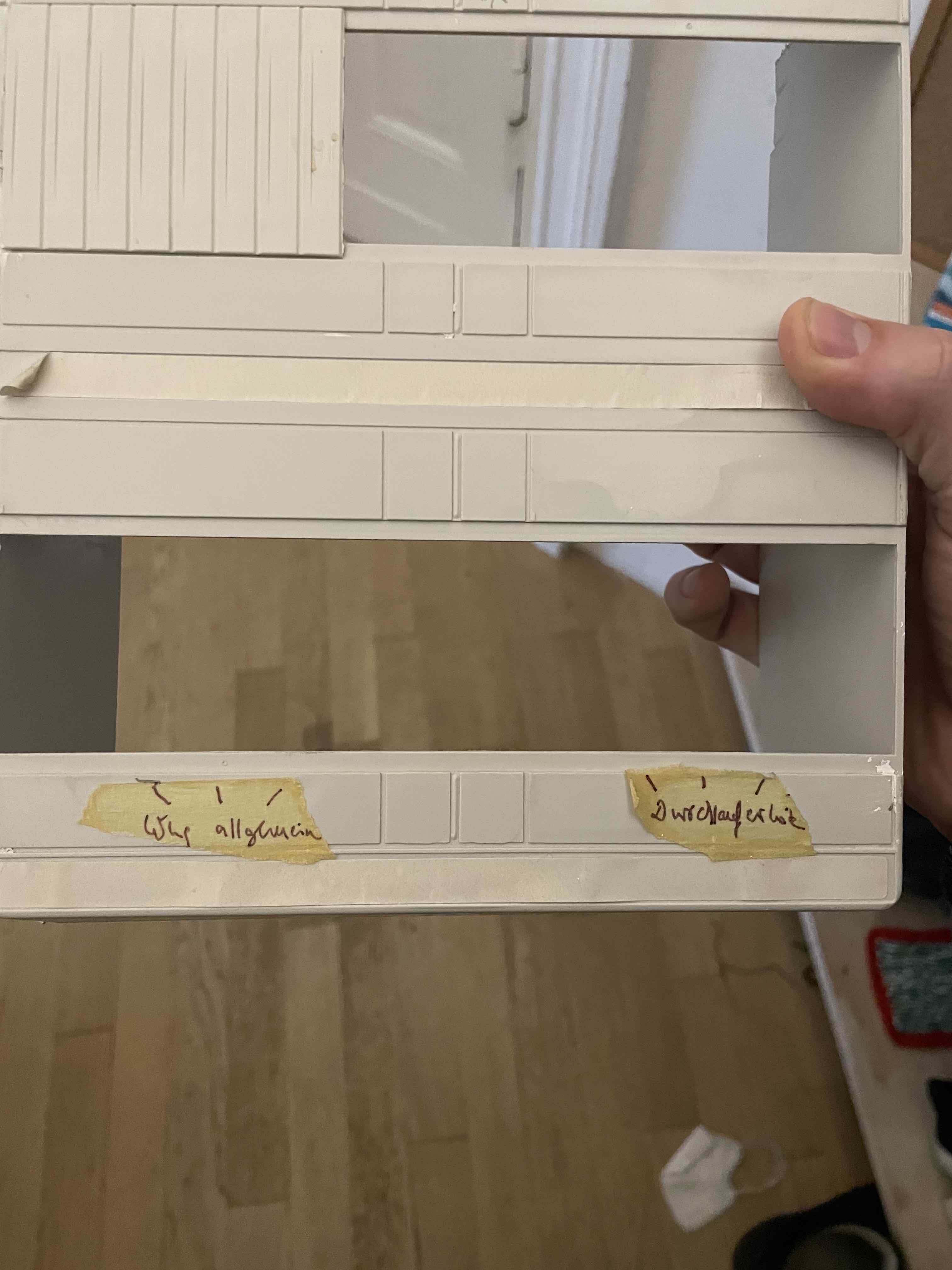
I have some trouble to figure out how it is wired. It’s a real mess. The panel labels the 7 fuses down the bottom with, from left, 1-3 being “Wng allgemein” which means “general house” and 5-7 being “Durchlauferhitz” which is the water heater; they are all take offs from 1-3 with an extra fuse. The middle one #4 is not labelled, and I thought it must be neutral but on closer inspection it is actually a take off of the second wire. So I think I have a delta system, right? Photos attached.
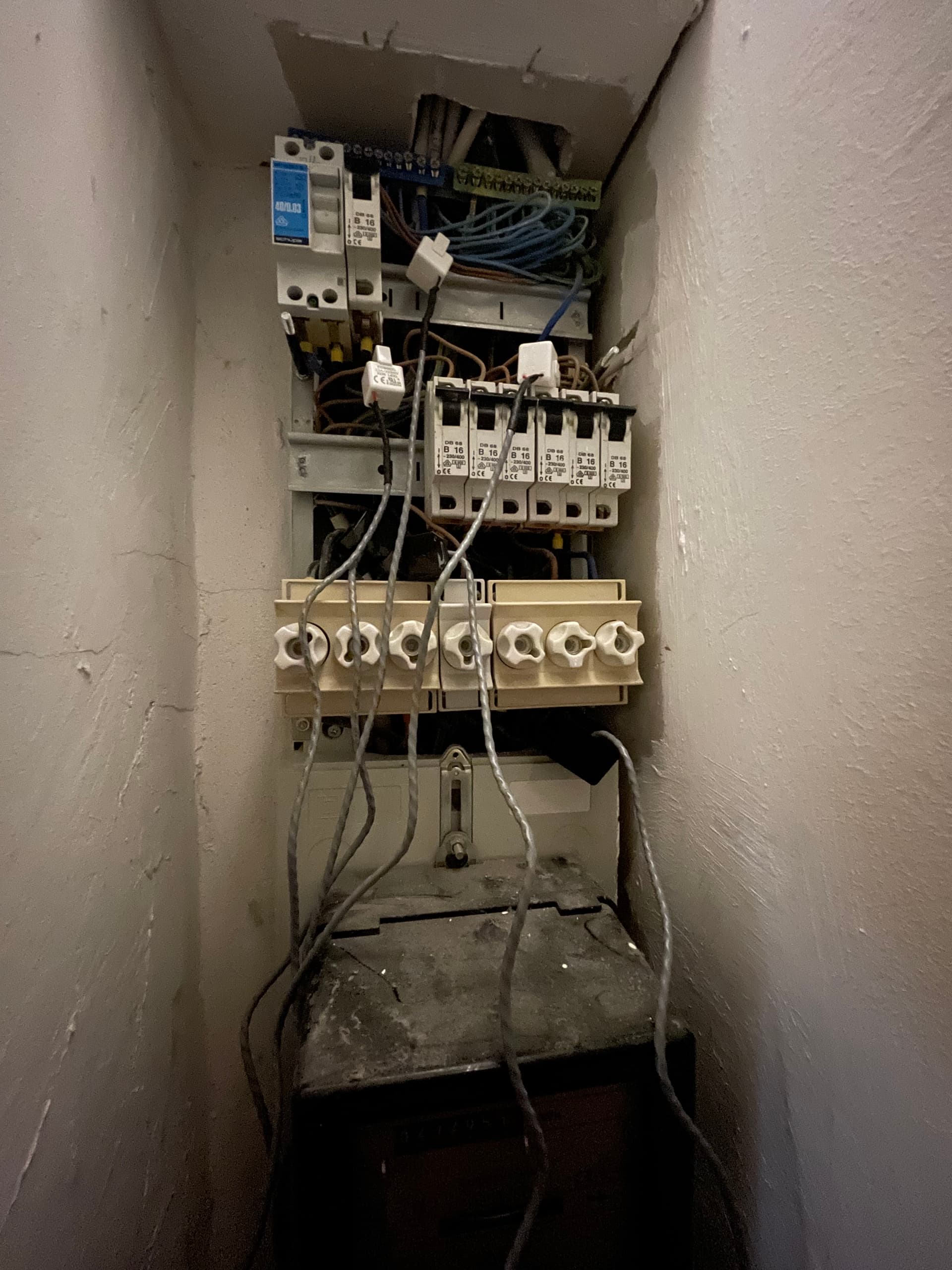
There’s not enough light to see wire colours, and I can’t see a 3-pole linked circuit breaker anywhere, what looks like a main switch is only 2-pole - all of which makes me think you need to measure voltages to be sure. I wouldn’t be surprised if the water heater alone was wired in delta, with the rest being connected line-neutral.
You should NEVER have a fused neutral. If the fuse blows, the circuit is not carrying current but it’s still live, which is potentially a very dangerous condition.
This gets more mysterious by the day.
The three wires are unfortunately all brown. There is an earth-coloured (green yellow) cable coming up from the meter which goes up to the huge messy earth panel up top left in the picture, so you might be right about the wiring. Also I can measure the water heater usage quite accurately with the current setup. The earth wire has no fuse.
Our flat is actually two joined in to one. The building is over a hundred years old and was renovated on the cheap after the one. Because of the two-flat situation, we have two meters. I would have thought about just buying three TXv4s but since I have six lines to measure I am not sure I have the budget. Bulk discount?
How can I help move things forward with the three phase version of the TXv4? @TrystanLea do you have a dev group for this ? @Robert.Wall I guess no point talking about firmware with you until the hardware works.
Despite my disappointment related to the incompatibility with my configuration I am impressed with how easy everything was to set up, and having realised that heating water accounts for a third of our annual consumption I am glad to have it working at all, even if a little poorly.
That doesn’t help us, unfortunately - a likely consequence of a ‘cheap’ job (cheap at the time but more expensive later to everything right). There’s little I can do until you measure voltages and can confirm that you do have 3 phases - or that you don’t. If each original flat had a single phase supply taken from different phases, it may well be that you have just two of the three phases.
Is the wiring visible where it enters the meters? If so, photographs of the two meters should also provide conclusive evidence.
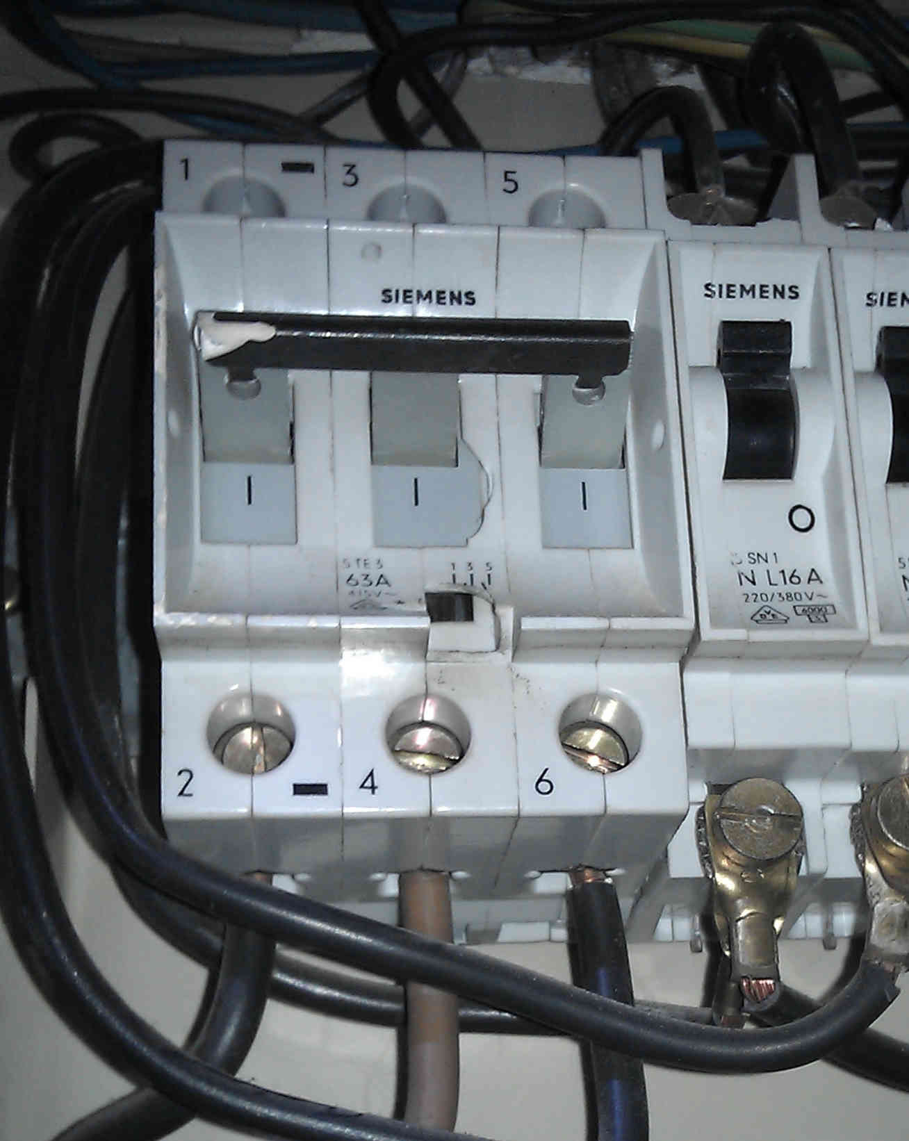
This is what a 3-phase main switch/breaker looks like:
And here is the terminal block of a 3-phase meter:
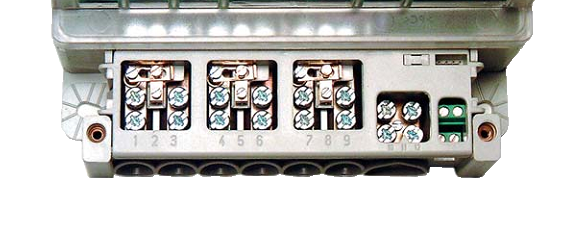
The first phase will be in on terminal 1, out on terminal 3, for phase 2 it is terminals 4 & 6, and for phase 3 terminals 7 & 9. The neutral is 10 & 12.
The earth wire must NEVER have a fuse. Its purpose is to blow the line fuses in the event of a fault to earth.
I doubt there is anything you can do at a distance. I’m working on the software, but it’s proving difficult if not impossible to achieve early expectations. I’ve no intention of releasing anything until I’m as confident as I can be that it is providing accurate results and it is as bug-free as possible.
I am quite sure we have three phases. On this meter we have the hot water which is a 18kW unit. One phase is measuring 6kW and I have two other wires to it, and I am getting very hot water. I simple calculation of the energy required to heat our winter water to temperature tells me that 12kW won’t cut it, and anyway why the three fuses to the water heater?
Furthermore we had an electrician install our oven-stove unit and he pulled in the three phases to it from the other meter.
The entering wires are all covered and some of the screws are such that they give tamper evidence. Not sure I want to fiddle around there. I do wonder though how the electrician did work on it. There must be a breaker under there for him somewhere.
OK was trying to get in the open source spirit.