Flash an SD with Latest version, installed on a Raspberry PI 2 and updated sucesfully via EmonHUB.
Installed the I2C LCD ok.
Prepared an Arduino UNO board and connected to Raspberry with the correct pins ( I think ) between Raspberry and Arduino.
Later updated the ATMEGA328 with AVRdude and it also seems to be ok.
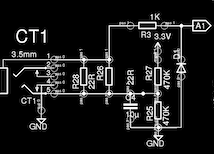
Connected the CT1 and Components to A1 Pin in arduino.
After power on, display shows IP, and version, wifi also works fine, but it does not show anything about detecting AC CT. Logging into EmonCMS, shows no inputs available.
Is your c.t connected when you power the Arduino? It must be (or rather, the 2.5 V bias must be), otherwise it is ignored by design.
Is your “emonPi” from the OEM Shop, or is it made from parts that you bought locally? I’m not clear whether you have tried to build an emonPi clone or an emonBase with a serial connection to an Arduino. Unless you exactly copy the hardware and software for the emonPi, the emonSD image probably won’t work without modification.
What information did you follow when connecting the various components?
What sketch is in your Arduino? Can you use your programmer to see what it is sending?
You cannot read power without the a.c. adapter and a measure of voltage. You can only have an approximation of apparent power (VA - volt-amperes).
Have you stolen the sketch for the AtMega from the emonPi on GitHub, or what are you using?
Are you reading a current with your Arduino sketch? How is it sending the data to the RPi?
This is the “update Emonpi” log. Everything seems to be ok, but may be it will help you to find the trouble.
After updating I was able to see 3 nodes in the input screen for a moment, but they said error and 0 readings or update. I deleted them and never appear again.
Also the boot sequence on LCD still showing only the Wifi IP, MTTQ Server not connected and the version, but can’t see the CT detection message.
I’ve installed the emonPi discrete sampling test sketch to the Arduino just for test the CT and seems to read values from CT correctly. It doesn’t have Voltage readings yet, and will need calibration. This are the serial print values read:
If it does not work then, I think you need to look at your connections again. Bear in mind what I wrote only yesterday in another thread “Beware: the emonTx has the serial pins labelled NOT according to convention. Transmitted data appears on the pin labelled “Rx” (i.e. it is looking for Pin Rx), received data should come in on the pin labelled “Tx” (i.e. it is looking for Pin Tx).” So you must ignore the entries for Tx & Rx in the column in the Wiki headed “emonPi V1.6 Atmega 328”.
You did remember to disable (comment out) the Radio module, or set RF_STATUS = 0; if you don’t have the emonTx Shield fitted?