Having trouble with my Arduino build. Voltage is working fine. But when trying to get current it is not working and unsure what I am doing wrong.
When there is nothing running my serial monitor is showing around 155. When something is running ( 2100 w kettle it jumps up one or two digits but not a lot of change.
I have a scope meter attached and it is saying I have 2.372vdc when nothing is running
Is that 155 W? And a 240 V supply? (I’m guessing as you’re in Australia.)
That should be 2.5 V d.c. but the difference is nothing to worry about. Have you built your analogue circuits according to the instructions in “Learn”, or do you have an emonTx Shield? Have you connected your c.t. correctly? And got the plug connections right?
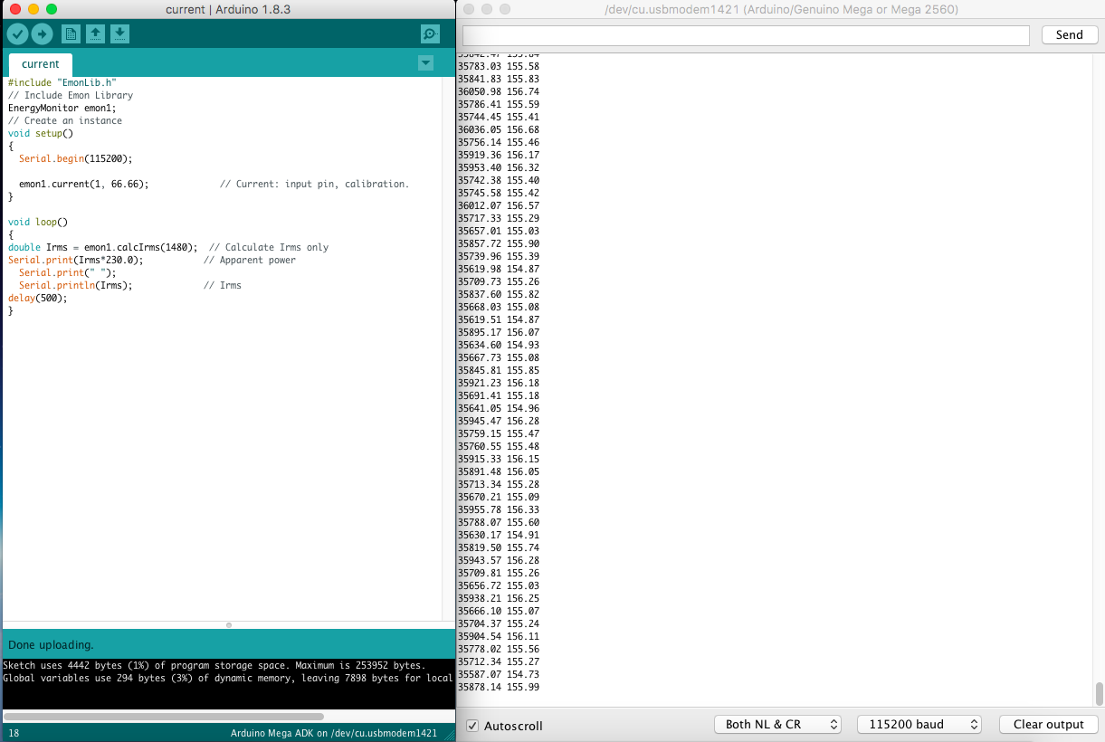
As far as i can tell everything is connected correctly. This is an arduino build. I thought i added a picture but it didnt work. Will add it now. But Irms is showing 155.
Either you have the wrong input pin, or your c.t burden is missing - or not 33 Ω, or there’s something else wrong with your sketch that I can’t see on the screenshot. Can you include/attach the complete sketch file?
What do you see if you short-circuit the c.t and burden (effectively have a 0 Ω burden)? It’s perfectly safe to short-circuit a c.t., but potentially dangerous to leave it open-circuit.
30 Ω vs 33 Ω will reduce the current reading by about 10%, you can easily compensate for that by changing the calibration. What I meant was the burden would have to be significantly larger - like open-circuit - to account for reading 10 × the true current (all other things being right).
Reading 155A implies you have a voltage across the burden of about 2.35 V rms. That implies 6.6 V peak-peak, which is more than the Arduino input can handle, so either you have no burden and the input is horribly distorted and clipping, or the calibration is way out. (“66.66” for your calibration means 66.66 A will give 1 V at the adc input pin.)
How does what you see there compare with the drawing here?
If the burden is OK, then the next thing to check is the d.c. voltage measurement. EmonLib reads the internal band-gap reference inside the Atmel 328P, and from that measures the d.c. supply voltage. If it gets that wrong, then the scaling of every analogue input will be wrong. It appears at the beginning of calcIrms( ):
   #if defined emonTxV3
	int SupplyVoltage=3300;
   #else
	int SupplyVoltage = readVcc();
   #endif
If it’s an emonTxV3, we use a fixed value of 3300 (mV), so you could easily substitute
int SupplyVoltage=5000;
there if you wished (and your d.c. voltage is 5.000 V!)
But first, I’d temporarily print that to check what value you’re getting. The band-gap’s initial value is not precise, 1.0 - 1.2 V, ±10% or so, so don’t expect 5000 exactly.
If that’s correct and the burden is correct, then I’m not sure where to look next.
I was using an external power supply and only running the analog wires back. So I changed that over and I just changed the int SupplyVoltage=5000;
for testing. I would like to print the exact value like you said. I am not exactly sure how to though. Can you point me in the right direction?
Which analog wires? I don’t understand which you mean.
You should do this only as a temporary measure, because it’ll print it for every call to emonLib.
Where you have int SupplyVoltage=5000;
below it, insert: Serial.print("Vcc = ");Serial.println(readVcc());
Of course, with the value of SupplyVoltage fixed, readVcc( ) gets the value it thinks the supply is, but it does not use it.