If you install any c.t. before you’re ready to connect and use it. you MUST short-circuit it until such time as it is connected.
1 Like
I knew there was something like that. I’d probably rig up a board of jack sockets to plug them all into to do that. Not happening for a while 
So if the CT is 30A and the average load is low in the range of 2 to 3A or lower (also loads are not resistive) to change Phase_shift to 1.9 from 1.7 and measure current first and the voltage after?
That will help, but if the installation conditions allow, you can use a multi-turn primary winding for your c.t. That will move the current you anticipate further up its operating range and reduce the c.t’s internal errors. You must divide the measured value by the same factor, so if you have 5 turns, the c.t. sees 10 - 15 A, and you divide by 5 to get back to the true 2 - 3 A.
You must set the phase error correction on a resistive load so that the power factor comes out as close as possible to 1.0
I will update my sketch to measure current first. I am in US so measurement cycles should be multiples of 60, so is 2040 okay. Or is there any better value? And then will measure voltage.
Right now I am using SCT-013-030 CT’s so I don’t think I can do any adjustments to this CT.
What model/brand CT’s you are referring to, I would like to take a look at them (something not too expensive).
For the resistive loads can I just set it to 1.0, or what do you mean as close as possible?
I wish I knew what you were talking about. Looking at your history here, it seems you might have an Arduino build. If you’re using emonLib and measuring only current, then you want a whole number (or as near as possible) mains cycles in your current sample. You need to know your sampling rate. If it’s running at the same speed as our emonTx does, then the numbers are here: Sampling rate of emonLib
You should check, because that only applies to you if it’s an Arduino Uno running at the same speed as the emonTx. If not, you need to time it yourself - the best way is to time a relatively small number of samples, then time (say) 2000 more, and look at the difference in the times.
When you get to measuring the voltage as well, that’s irrelevant because emonLib can count mains cycles, so you set the number of cycles, not the number of samples.
But there’s nothing to stop you having a multi-turn primary winding - provided there’s enough slack in the wire you’re putting the c.t. on. If you just put the c.t. on a wire, that wire is a single-turn primary winding. If you loop the wire back on itself outside the c.t. and pass it through again in the same direction, that’s a 2-turn primary winding. And so on.
You can’t set the power factor, you adjust the PhaseCal value so that the power factor comes out close to 1.0.
I do use Arduino Mega with emonLib. I am measuring Voltage and Current, 8 CT’s in total
you totally lost me here sorry. This the code I have part of it
Setup:
emon4.voltage(0, 100.1, 1.7);
emon4.current(4, 30); // Kitchen combined
Loop:
emon4.calcVI(20,2000);
float realPower4 = emon4.realPower;
float Irms4 = emon4.Irms;
I am mainly concerned about realPower. But it is nice to have accurate Irms for calibration, bebugging processes.
Is there a way to improve my code? Do I need to alter anything in the emonLib.h file?
I will see if there is enough slack to wind it few more times around the CT.
so something like this: emon4.voltage(0, 100.1, 1.0); or what other better way to calculate it?
I really appreciate all your help and input.
The whole basis of the maths is to get an accurate average, you need a whole number of mains cycles. The Arduino Mega takes many individual current samples per cycle, so you need to know that number so that you can arrange the correct number of individual current samples to cover an integral number of mains cycles.
It’s immaterial anyway because you also write
and calcVI( ) works over mains cycles - the “20” parameter. means 20 half-cycles, so 10 full cycles.
No, this is how emonLib is designed to be used. But you will need to add a line.
No, you should not touch, and should have no need to touch, the library code itself.
It’s not practical to try to calculate it, you will need fairly special instruments for the measurements which the calculation needs. What you must do is display the power factor emon4.powerFactor and then try different values for the 1.7 in
until the value of power factor comes as close as you can get it to 1.0. I cannot tell you what the value should be, 1.7 is most likely wrong, because that is for the 100 A c.t, a UK a.c. adapter and an emonTx – and you don’t have any of those.
You will probably find you need to have a slightly different value for PHASECAL for each channel.
What line do I need to add?
What about non resistive loads? Do I still adjust 1.7 till power Factor comes as close to zero?
The one I told you to a few lines further down, to display power factor.
No - but you could adjust for zero power factor, if you could get a purely reactive load. The problem is, you won’t be able to do that. You can easily come by a purely resistive load - like an electric heater that does not have a motor in it - a kettle. By definition, the power factor is 1 for a resistive load. You will initially read a number less than 1 due to errors in the transformers, etc. You set PHASECAL to remove those errors. Once set, you should not change it again. When you’ve done that, the power factor displayed should be correct for the load you have connected, whether purely resistive or not. If you don’t understand power factor, take a look at “Learn” and A.C. Power Theory.
there is not enough slack to wrap the wire around CT few times. I could go with the lower rated CT, like 15A. That should give better accuracy (than current 30A CT’s) at low power consumption periods right?
I looked in my sketch and I can’t figure out where I can modify the order where current to be measured before the voltage.
is it in the setup portion?
emon1.voltage(0, 100.1, 1.7);
emon1.current(1, 60); // MAIN A
emon2.voltage(0, 101.1, 1.7);
emon2.current(2, 59); // MAIN B 571 was good on heavy load (58.8 with 34oms resistor
emon3.voltage(0, 100.1, 1.7);
emon3.current(3, 28); // REFRIGIRATOR
or something in the loop
emon1.calcVI(20,2000);
emon2.calcVI(20,2000);
emon3.calcVI(20,2000);
float voltage = emon1.Vrms;
float realPower1 = emon1.realPower;
float Irms1 = emon1.Irms;
float realPower2 = emon2.realPower;
float Irms2 = emon2.Irms;
float realPower3 = emon3.realPower;
float Irms3 = emon3.Irms;
please advise,
thanks
That’s correct.
That figures, it’s actually in emonlib.cpp that you need to change it - but only do so if you can’t get a reasonable result as it is by changing the “1.7” number in emon1.voltage(...) etc.
In emonlib.cpp, swap the order of these lines (about 105 lines down the file)
    sampleV = analogRead(inPinV);            //Read in raw voltage signal
    sampleI = analogRead(inPinI);            //Read in raw current signal
awesome, thanks for a quick reply
one more question. I was rereading Learning section about measuring individual circuits in US. I found that I was for years measuring voltage for some of the circuits wrong.
I have instances like:
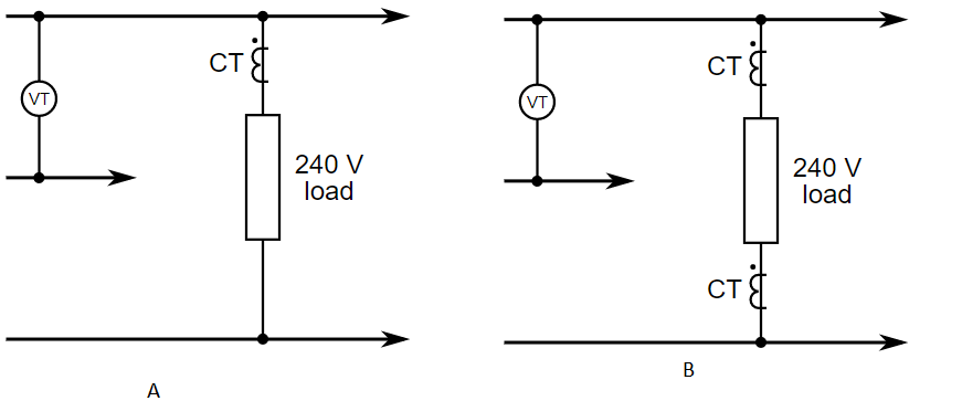
in A I was measuring voltage only at 120v and just doubling by realPower*2
and in B I was also measuring voltage at only 120v and summing both realPower’s.
In both instances I had to be using 240v instead of 120v(if I understood it correctly). To get correct voltage reading, do I just modify x in the line below till voltage reads 240v? or is there a better place to double the voltage?
emon5.voltage(0, x, 1.7);
Also for the whole house total power, was the same scenario as in B. Where voltage was only 120v  if I understand it correctly it had to be at 240v if I am summing both realPowers coming from individual CT’s measuring each phase?
It sounds as if you are totally mixed up.
In (a) you are measuring between wires that are nominally 120 V apart, but your load is seeing 240 V. You are measuring the current, so you need to double the answer on the assumption that your load really is seeing double the voltage that you measure.
In (b) you are again measuring 120 V, but this time, you are reading the current twice, so that is where the doubling comes in, so you should be adding the currents or the powers, with no doubling. Or maybe look at it another way: you can connect the middle of your 240 V load to the neutral and nothing changes, so the “top half power” is the top c.t. current multiplied by the voltage, and likewise the “bottom half power” is the bottom c.t. current multiplied by the voltage, assuming the voltage across the bottom half is the same as the voltage you know. Add the two powers to get the total.
So that is in fact absolutely correct.
The N.America system is totally different to anywhere else, because you have a single phase but a choice of voltages. If we had two voltage inputs on the emonTx, undoubtedly the correct way would be to measure both voltages and add them before multiplying by the current for 240 V loads, but multiply the appropriate voltage by the current for 120 V loads. But the emonTx was designed for (IMNSHO ![]() ) the much more sensible UK domestic system where everything is 240 V, so it has but one voltage input.
) the much more sensible UK domestic system where everything is 240 V, so it has but one voltage input.
I think you should leave the voltage reading the 120 V accurately, and carry on as you are, because from what you’ve written and without a complete wiring diagram of what you’re measuring and where you’re measuring it; and the maths you’re doing to get the powers; you’re actually doing it right.