Just wanted to double check that I’m on the right track in terms of hardware to purchase before I go ahead and do so.
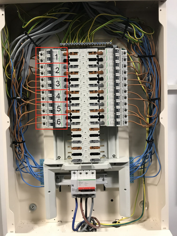
There is a distribution unit in my office which supplies power to a number of racks of equipment. Each rack is supplied by any two phases from a 3-phase supply, as per this photo (each number is an equipment rack):
As a minumum I need to monitor the power consumption of a single rack, but I’m hoping I can use an emonTx with four clamps to measure two racks at a time (each rack has 2 x 16 amp supplies).
So based on that, my intention is to buy 1 x emonBase, 1 x emonTx, 4 x CT clamps and 1 x AC-AC adapter. Could someone confirm this is correct?
I read that It’s likely the emonTx will need a separate power supply rather than using the AC-AC adapter. How will I know if this is the case? Inaccurate/unreliable measurments?
I think I don’t understand what you need to measure.
You have 6 equipment racks.
Each rack receives two phases - does that mean it has 2 supplies @ 240 V, or one at 415 V? What I’m getting at is, do you need to measure each phase into each rack, or is there no neutral (or the neutral current is insignificant)?
Where is the data going after you’ve got the measurements?
How well balanced are the phase voltages?
A few observations:
The emonTx is inherently a single-phase device. If you’ve got 12 wires spread across 3 phases, it makes more sense to me to allocate an emonTx per phase. If you do that, and you might need to if the phase voltages are not sufficiently close, you can have 3 × emonTx, each with 4 c.t’s and an a.c. adapter.
You don’t need to use the 100 A split-core c.t. A ring-core of lower rating will be smaller, more accurate, especially below 16 A, and it looks easy enough to drop the wires out of the terminals to install them. (The ‘shop’ c.t. is only spec’d down to 10 A.) With a bit of fiddling, you can change the c.t. burdens to suit the c.t.
I know about two smaller 20 A ring-core CTs: I believe Robin Emley uses either the 20A:10mA version here: http://www.yhdc.com/en/product/425/ or this 20A:10mA one http://eppep.com/?action-viewnews-itemid-140364 from http://www.ebay.co.uk/itm/281436762683?_trksid=p2059210.m2749.l2649&ssPageName=STRK%3AMEBIDX%3AIT (Those URLs appear to be dead) or the YHDC TA1020 (http://m.en.yhdc.com/product/503.html) looks to be suitable (with a burden resistor change), though it is intended for pcb mounting.
Slightly less accurate is the ‘shop’ split-core YHDC-SCT006, which is OK if you don’t need the full 16 A range.
The emonTx will only need a 5 V USB supply if your mains voltage is well down, or you’ve got extra loads (e.g. temperature sensors) on it.
Incidentally, you must neverclamp a c.t. with a ferrite core onto its cable - you risk shattering the core. It must always be a loose fit.
Thanks for the reply Robert. Concerning your points:
there’s actually 12 racks but I have just illustrated how the first 6 are connected within the box (7-12 are wired in the same way on the right hand side of the panel).
each rack has 2 x 240V supplies and two neutrals which are connected back to the 3-phase neutral - from what I can tell from looking in the box. Hence why I think I need two clamps per rack.
data would go to emonCMS running locally on the emonBase
not sure. Would it be sufficient to measure the voltage of each phase to find out?
Three emonTx would be good but two factors I need to consider are cost and also having 3 x AC adapters which currently there are not enough sockets for.
The measurements don’t need to be super accurate - 5-10% tolerance would probably be ok. I didn’t know 100A clamps weren’t good at low current. What sort of error would be expected measuring a few hundred Watts? The alternatives you’ve mentioned look like they can’t be clipped on and I don’t really want to be disconnecting wires. Also the less customisation the better to be honest.
You can’t expect the best advice if you only tell half of the story. Just saying…
So it sounds as if you need to treat each rack as two separate items for measurement - even though for display purposes you can lump the readings together in emonCMS (which is why I asked about that).
One reading, if the voltages were a long way apart (i.e. at the edge or outside your acceptable accuracy band) would be enough to say you needed to monitor all three, but alas the converse isn’t necessarily true. It’s going to depend largely but not totally on how your total loads are balanced - and to a lesser degree on your neighbours on the same local substation transformer.
Every c.t. ever made is inaccurate at low current - it’s inherent in the way the magnetism in the core works. The only difference is what ‘low’ means as a percentage of the rating, and that depends on the grade of the c.t. A ‘revenue’ grade will go proportionately lower, and cost disproportionately more.
I can’t read the rating of your breakers, so I don’t know the current you expect to measure - but as you say “a few hundred watts”, I’m guessing 3 A max? You’re definitely pushing the limits with the 100 A c.t., both from the c.t’s point of view and the ADC’s – you’d be better off with the SCT006 - the two I tested (the report is in ‘Learn’ - along with one for the SCT-013-000) started getting iffy at 50 mA for linearity, but were still OK for phase error.
You realise that you can measure the sum of the currents on the same phase by putting the c.t. around more than one phase conductor?
That’s the difference between a “ring core” and a “split core” c.t. Ring core are inherently more accurate and they don’t have the possibility of introducing an unknown and variable air gap in the magnetic circuit, and that can have a huge detrimental effect on the accuracy.
You’ll probably still need to change the 4th (high sensitivity) c.t. input on the emonTx - especially if you choose the SCT006.
As you have so many channels to monitor, would not an IoTaWatt system make more sense?
As @Robert.Wall said, if your purpose is to determine what each rack is drawing, a single CT on each pair of wires will do that. If you want to know what each supply is drawing (perhaps for power balancing), you need a CT on each, but I think you may struggle to fit them all in!
If you do go for an IoTaWatt (I have never used it), I think you could simply use that +CTs and self host an instance of EmonCMS.
I’ve had a look through your reports and as you say it seems the SCT006 is what I need. This would require no hardware change to the emonTx except for the burden resistor on the 4th input, a firmware change would also be needed for the 3-phase setup and because of the change in CT clamp, if I’m not mistaken?
Each breaker is rated at 16 amps and I would guess each one would have a load somewhere between 1-10 amps (but this is part of what I’m trying to determine by measuring!
What I’m a bit confused about is that it seems the 100 amp clamp is standard in the shop even for measuring solar, which is typically up to only 16 amps (and of course solar output is often significantly lower than this). Indeed I was given for Christmas a kit for monitoring my own solar setup. So this monitoring setup will have the errors associated with using the 100A clamp?
Yeah but given I want to measure the racks independently and each one is fed by two separate phases, unfortunately this isn’t beneficial.
I hadn’t considered an IoTaWatt. Having looked at it, it does look ideal but the issue I would have is connecting it to a Wifi network. My office has two Wifi networks: one requires a security certificate on every device that wishes to connect to it and the other has a login screen once it’s been connected to, so I think it’s a no-go
Correct, irrespective of the choice of c.t. - unless you’re interested only in current, and not power. The standard sketch assumes the same voltage reference for all four current inputs in order to calculate real power. The 3-phase PLL sketch derives the phase reference for the other phase(s) by delaying the first phase, but it still has no alternative but to assume the voltage amplitude remains the same across all three phases.
If you go back to the report, you’ll see that the phase error has increased due to the increase in load on the c.t. So although you’re making things better for the ADC by increasing the voltage across the burden by increasing its value, you’re making things worse for the c.t. itself. The SCT006 is somewhat better, but not as much as you’d expect at a first glance.
I threw that in, in case you didn’t know that trick, and at some point wanted a total of several racks.
And if you can identify the neutrals, you could measure those instead.
That depends on the PV setup. True, many do produce less than 16 amps, but I suspect
(from perusing the systems listed on pvoutput.org, thee are many that do.
On a sunny day, my system routinely puts out 33-35 Amps. While that’s not in the ideal part of
the 100A CT response range, it’s a tad more than 16.
Could you ask the IT dept to create a WiFi network that would only allow that device to connect by mac address? If the monitoring is business critical, they should at least consider how they could facilitate it.
Alternatively use an RPi in AP mode to create a WiFi bridge to a wired network (never tried that but off the top of my head cannot think why it should not work).
It’s a feature of the legal environment. In the UK, it’s a lot less hassle to connect a PV system of less thatn 16 A (actually 3.68 kW) than it is one greater. Search ‘G83’ if you’re interested in details.
So based on your answers I’ve concluded that the hardware I will need is what I originally suggested, but instead of 4 x 100A clamps I will use 4 x 20A clamps. I will need to change the firmware and also replace the 120 Ohm burden resistor on the 4th input with a 22 Ohm resistor, which I believe is R18. The accuracy of this setup will be determined largely by the voltage difference between the phase using the AC adapter and the other two phases.
It’s very easy to identify - it is the larger SMT component immediately behind the socket, with holes to accept a wire-ended replacement at each end (which will be R16 - shown on the circuit diagram but not called off on the BoM).
I will try and talk to our IT guys about it before going down the emonTx route, but I suspect it will be a struggle getting them on board especially as it is not business critical.
My only outstanding question (which is not related to my original post) is the setup for measuring my solar. I have an emonTx shield and 100A CT clamp (christmas present as mentioned earlier) and I’m not sure wheather this is going to be an accurate measurment setup. Would I be better off with the 20A CT and is it compatable with the emonTx shield?
Did you mean emonTx? The emonTx uses 433 MHz to report back to the emonBase, and if use an Ethernet cable, or if I understand correctly, you equip the RPi in the emonBase with a keyboard and screen, you don’t need a WiFi network.
Maybe - if you can find a 20 A c.t. with a 50 mA output, or you change the burden resistor to suit a different c.t. The problem with c.t’s and the shield is it runs off 5 V, not the 3.3 V of the emonTx, so to fully use the ADC’s input range, you need about 1.6 V rms across the burden at the maximum current you will be measuring. And that is running close to or outside the VA rating of many of the readily available small c.t’s, a lot of which are only good to 0.333 V rms.
As far as I know only Glyn here has any detailed knowledge of the Ioatwatt. Bob Lemaire, its creator, can now be found at https://community.iotawatt.com, he has set up a dedicated forum for IotaWatt, if you post your question there I’m sure he will get back to you quickly.