EDIT: after separating a few shielding common wires and having no shielding to ground i don’t lose communication anymore, voltage fluctuation is better but still make one module go crazy and balance.
The worse comunication is the more voltage fluctuates, i have seen up to 4.5v …
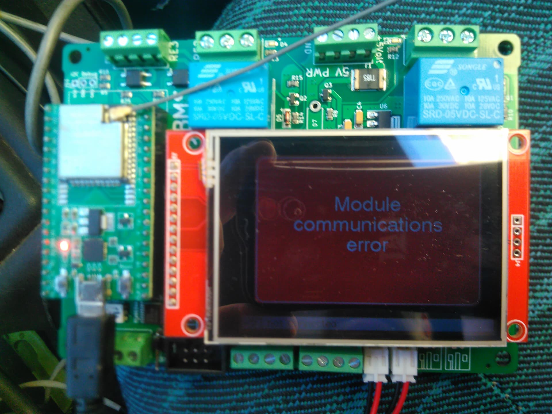
So i have a 32s3p battery for my electric car. (Redirecting...)
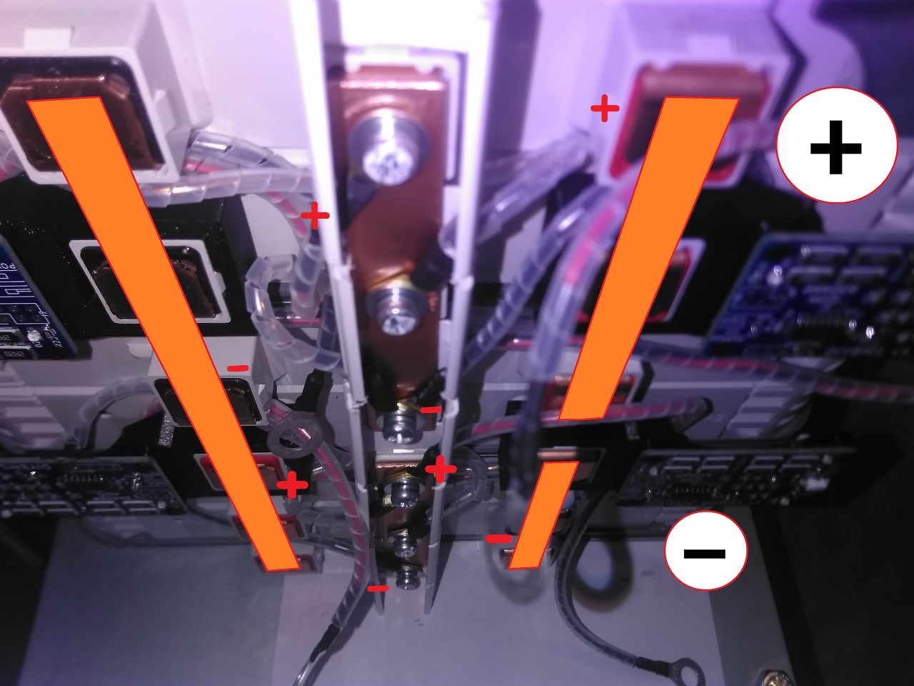
Each bms is conected in a way that all 3p have the same lenght of wire to it.
Also there are temperature probes screwed in the terminals but don’t worry about that.
So the problem is that when i charge i lose all communication and the voltage goes up too much because the battery is 260Ah and charging at 9Ah it could not go from 3.8v to 4.2v.
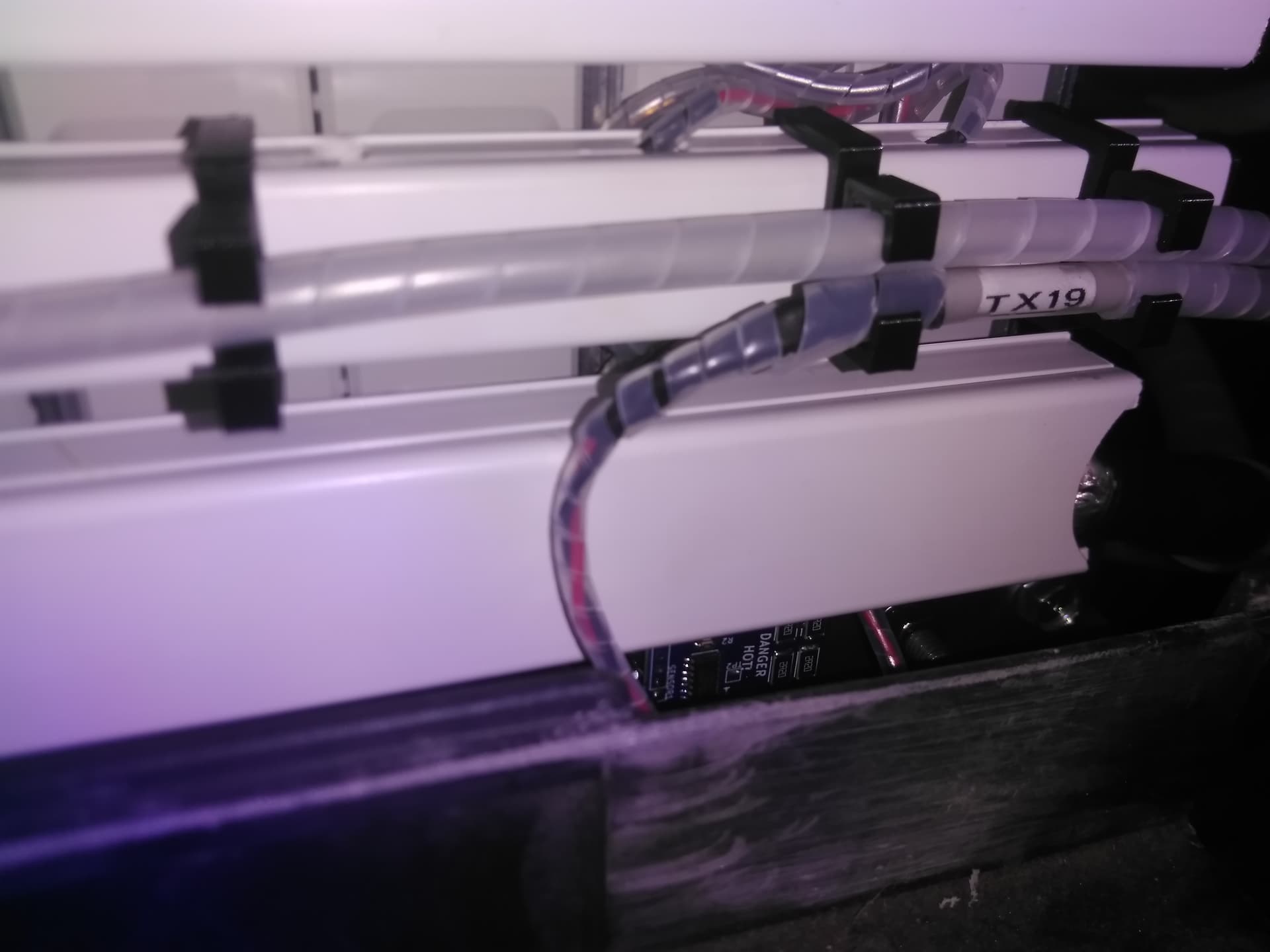
All the cables are twisted.
All the cables until the last 10cm (when they go to the modules) are shielded.
The shield is grounded to the car chassis (negative) close to the controller.
Any idea of what i can do next?
I can’t charge the car but i can drive it, sometimes one module goes up 0.2v when i accelerate 
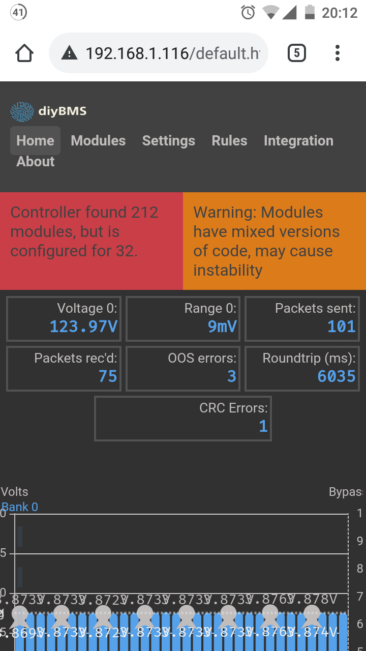
I only had time to test all the packs individually and they work perfectly, only the front pack has 10 crc errors out of 350 packets,
the rear and the middle pack show no errors while charging at 20Ah.
Next i will test the cables from pack to pack and see if i find the one trat cuts communication.
The strange thing is that only if i connect all packs to the bms controller they will go crazy while chanrging and start balancing the first cell of each pack because it shows more than 4.2v, but connecting one pack do the bms no cell or bms module goes crazy…
New tests today i reached a conclusion.
Working only on the front pack rx0 to tx7 i have 8 modules with the same latest code,
the good big controller also updated.
The worse the comunication is the worse is the voltage fluctuation on the 1st cell of the pack.
This should not be possible but:
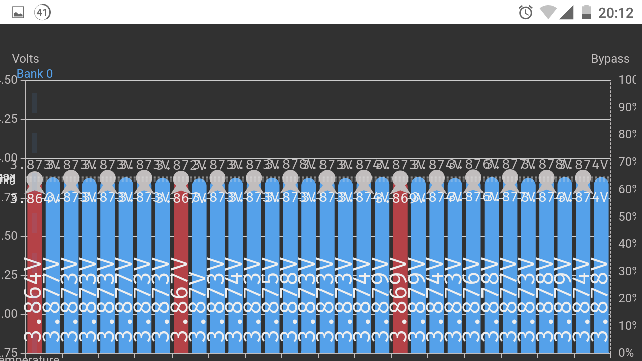
-When the controller is conected directly to the pack plug the first cell fluctuates from 3.849v to 3.858v when charging at 20Ah.
-When the controller is conected with 5mt+2.5mt cables on rx and tx the first cell fluctuates from 3.849v to 3.929v when charging at 20Ah.
If i concect to the other packs at the same time there is one cell that jumps to 4.2v or 4.5v when charging and that is just impossible.
How can the communication affect the voltage reading?
glad to see so many people interested in this problem 
So i finally finished updating all the modules to the same code and i have the same results.
But new testing reveals that if i connect the shield (from pack 1 to pack 2) to car ground i lose all communication and the first cell of pack 2 starts balancing(i can see the red balancing bar and module temperature goes up).
If i remove all shields and just let the wire loose the first cell of pack 2 fluctuates from 3.8 to 4.08 but does not go to balancing (4.15v).
Today i will conect a wire to that cell and see what the real voltage is, but i suspect it’s around 4.8 like all the others and like when i conect the bms to only one pack instead of 3.
I pulled wires from the first 3p of the rear pack that fluctuates when charging to get the real voltage reading to remove any doubt…
Redid all bms comunication wiring, rerouted all the cables, shortened cable 3 from 7m to 4m and cable 2 from 5m to 4m, removed all common grounds to each of the 3 packs, using now a different superseal conector for rx and tx, grounded all long comunication cables to the RX of the module that recieves the signal and now it works no voltage fluctuation on any cell while charging at 20A.
I will not be updating the modules to the new code with averaging, it would take a few days and i just finished rebuilding it all.
Roundtrip is the exact same time around 6030ms.
Anyway, 1 month of my life just lost, i still don’t understand how a noisy signal with no errors will make a single cell act crazy and give out a random voltage, and we may never know…