curious is the the enomtx shield incompatible with a lcd_l2c on a uno board. as it freezes when it reaches lcd init , or do i have to use the basic route of just an LCD screen, – what i/o pins are free on the shield
I know nothing of the LCD, you can find the I/O details for the Shield on the Wiki. You have to go via Building Blocks on the “old” site:
Resources > Scroll all the way down to Fundamentals - Building Block Resources > Resources (in the banner) > Hardware Wiki (in the dropdown) > emonTx Arduino Shield (in the contents list) > emonTx Arduino Shield (in the table).
Robert,
If I click “Resources” on the old site’s Site Map, I can’t see anything about “Fundamentals” or “Building Blocks”. And I have no idea about how to navigate to the Wiki …
1 Like
That is the complete route from here to the Shield Wiki on the old site.
Aha, thanks Robert. I’d never have worked out that linkage on my own.
So “Resources” on the Site Map of the old site is not the same as “Resources” on its banner. And “Resources” on the new site is different again.
Sadly, I’m rapidly losing interest in this venture …
I think the Arduino Uno uses A4 and A5 for the I2C bus, which is also used as analog inputs for the EmonTx shield, so it would seem the EmonTx shield is not compatible with any shield that uses I2C (at least on the Uno).
I think the path is Old Fourm > Resources dropdown menu > Hardware Wiki. Scroll down & look for EmonTx Arduino Shield
So why isn’t the Shield listed under Resources directly on this forum, when most other things are? Whichever way you look at it, it’s not clear and old hand Robin has found.
I suspected something like that - it’s a near-repeat of the problem a few years ago. (From memory: with a particular clone and an Ethernet Shield? - something like that.)
hi i bought a emontx shield and it seams to gives erroneous reading
example:
I think it has probably a bad resistor on port 3
-0.00 -26.97 6042.74 28.17 121.67
-0.00 -27.37 6056.80 27.26 121.86
-0.00 -26.93 6038.67 27.82 121.74
-0.00 -27.55 6034.19 28.03 121.59
-0.00 -27.12 6027.13 27.83 121.71
-0.00 -26.81 6042.26 27.63 121.53
-0.00 -27.46 6031.58 28.11 121.77
-0.00 -27.37 6030.33 28.09 121.55
-0.00 -27.30 6017.31 27.72 121.37
-0.00 -27.43 6044.73 27.77 121.67
-0.00 -27.81 6033.74 28.42 121.85
-0.00 -27.78 6056.13 27.71 121.79
-0.00 -27.22 6036.45 28.08 121.81
-0.00 -27.51 6047.02 28.55 121.91
-0.00 -27.66 6056.78 28.21 122.03
-0.00 -27.32 6063.59 27.66 122.20
-0.00 -27.47 6073.10 28.15 121.83
-0.00 -27.98 6064.05 27.55 122.01
-0.00 -27.62 6069.62 27.98 121.94
-0.00 -27.41 6071.97 27.44 122.06
-0.00 -27.30 6066.59 28.39 121.95
What do those numbers mean? I have no idea which sketch you are using.
Please read the FAQ, because that tells you what you need to tell us so that we can help you.
It would be helpful if you put all 4 CTs on the same cable and told us what current, power and voltage you expected to see. Have you swapped CTs between channels - does that reveal anything?
oops sorry I should of said it had a +27 watt load on 2,3 and4 all of on the same cable, here a sample with zero load on ct 2,3 and 4 that is with the base sketch - Shield_CT1234_Voltage_SerialOnly port 3 always reading in around the 6000 mark
0.00 0.00 6157.50 0.00 122.75
-0.00 0.00 6161.65 0.00 122.65
0.00 -0.00 6155.85 0.00 122.68
0.00 -0.00 6150.88 -0.00 122.69
0.00 -0.00 6153.79 -0.00 122.62
-0.00 0.00 6152.94 0.00 122.55
-0.00 0.00 6040.95 0.00 122.70
-0.00 -0.00 6132.23 -0.00 121.73
Why is your voltage only 120 V? What is your nominal mains supply voltage?
What does Input 3 read with the CT uplugged? (You should see the values slowly decay to zero.)
It might be the CT’s burden that is missing or open-circuit, but I rather doubt that you would get numbers that big even so. But it’s easy to test. Look at the pcb immediately behind the CT’s socket, and you should see a pair of holes for a wire-ended resistor, and between them on the other side of the pcb a SMT 33 Ω resistor, R17. Is the resistor there? If you have a multimeter, can you check the value? Even if it appears correct, if you have any small (i.e. any value below about 300 Ω) wire-ended resistor, or even a wire link, temporarily insert that into those holes and see what happens. If the numbers fall to a “sensible” value, by that I mean significantly less than 6000 (zero for the link!), then it looks as if that is indeed your problem. If not, I’ll have to think again.
I notice you’re the same poster having compatibility issues with the emonTx shield and your I2C LCD shield. Were the above measurements taken with the LCD shield connected? If so, do they get better when you remove it? If so, see my reply to your other thread (I don’t think the two shields are compatible at least on a Uno).
Threads merged, as it would appear to be the same problem.
humm not really the same problem not sure why you merged it, perhaps related as i get the bad reading on ct 3 even before trying the lcd _l2c as i just wrote a program that was operating on the remaining working ports…
lcd l2c only uses 4 wires - 5v, grd, scl and sda-- no a4 o5 involved and was curious if the lcd -l2c is incompatible with emontx shield
all measurement for ct3 are done on on a a empty arduino and emontx only thing connected are the CTs ( no LCD shield or lcd - l2c connected)
why 120 volt Canadian voltage ranges from 120 - 124 normally 124 volts for my province
the 6000 value is the same with ct plugged in or not, all it does in fluctuate around the 6000 range by 10 - 20 % and never decays to zero
I compared it the resister value where you said and it is relatively close to the range of the other ones +/- 33.3. I also tried a second resistor inserted 33 value same reading does not change
if i use the no volt sketch it decays to 2000 instead of 6000
as to all the errors tried it on 3 different uno borard all from different manufactures all the same issues
If the same person is having two problems with a common piece of hardware, it makes a lot more sense to me to have them in the same thread, so that everybody sees the full picture.
I had no idea where in the world you were, hence the voltage question. I’m assuming all the time that you haven’t altered the sketch in any way.
With the Shield_CT1234 sketch, you say the CT3 power shows around 2000? Which ac adapter are you using?
Have you checked the pcb for obvious manufacturing faults - I’d be looking in particular at the track that goes from the burden resistor to the processor, and looking for a hairline break or a whisker bridging to an adjacent track. Have you checked continuity between the burden resistor and the Arduino pin?
What power value do you get with the Shield_CT1234 sketch with the Shield absent ? (You’ll need to comment out the rf12_… and send_rf_data… lines, else the sketch will hang.)
With the Shield & CT connected, does the voltage on the burden resistor sit at around 2.5 V d.c?
The software filter should take out the d.c. bias whatever the voltage the input sits at, but this would be a final check.
On an Uno, SCL is A5 and SDA is A4 (see https://www.arduino.cc/en/Reference/Wire) or if you prefer to use the ATmega328P datasheet:
PC4 can be ADC4 or it can be SDA but it can’t be both (ditto for PC5, ADC5 and SCL). When you’re connecting your lcd_I2C to your Uno, where do you connect it, if not to A4 and A5?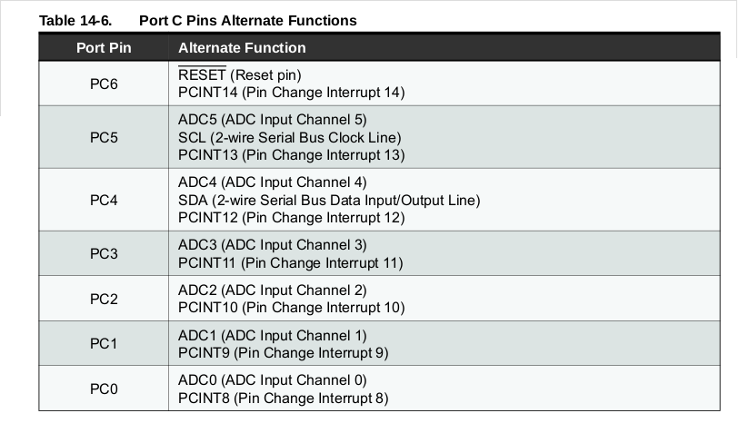
Those two shields may well work together if you choose an Arduino that has the I2C pins somewhere else. That’s not an iron-clad guarantee, you’d need to check all other pins usages for conflicts before you commit to replacing your Uno with something else. But one thing is for sure, an Uno can’t do any I2C (not just LCD shields) when it’s hosting an emonTx shield.
But you’re right… if there’s nothing connected to SDC and SDA then that can’t be the source of your bad readings.
okay i check the traces they seam fine i can not see any thing visible wrong, and when i check for continuity from the burden resistor to the corresponding analog pin it say it fine… would there be a pcb layout for this board somewhere, as it would be easier to track the traces.
perhaps one of the other grouping of cap resistors are bad for ct 3 i tried to check thier reading but i get nothing … it just zeros out , I guess how they are . configure make it impossible to check.
what the bare minimum pins require to boot this board.
I assume a0- a4 ( as 5 appears not to be used) and 5v and ground and pin 9 for the led . i will try that and just swap positions for ct 3 to ct 4 and if the fault move to ct4 position then we know the fault is hardware.
thanks dBC i did not know that, so as it appears a5 is not used, if ( i had fully working board) all i would need to do is cut the trace, pull pin for a4 or remove the burden resistor and then l2c would work by disabling ct4