AC present
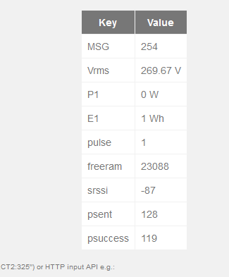
MSG:1,Vrms:268.42,P1:4,P2:1,E1:0,E2:0,pulse:1
MSG:2,Vrms:268.59,P1:7,P2:0,E1:0,E2:0,pulse:1
MSG:3,Vrms:268.53,P1:20,P2:0,E1:0,E2:0,pulse:1
MSG:4,Vrms:268.51,P1:19,P2:1,E1:0,E2:0,pulse:1
MSG:5,Vrms:268.74,P1:13,P2:0,E1:0,E2:0,pulse:1
MSG:6,Vrms:268.89,P1:10,P2:0,E1:0,E2:0,pulse:1
MSG:7,Vrms:268.64,P1:7,P2:0,E1:0,E2:0,pulse:1
MSG:8,Vrms:268.11,P1:5,P2:0,E1:0,E2:0,pulse:1
MSG:9,Vrms:267.83,P1:4,P2:0,E1:0,E2:0,pulse:1
MSG:10,Vrms:267.54,P1:4,P2:0,E1:0,E2:0,pulse:1
MSG:11,Vrms:267.69,P1:3,P2:0,E1:0,E2:0,pulse:1
MSG:12,Vrms:267.96,P1:3,P2:0,E1:0,E2:0,pulse:1
MSG:13,Vrms:267.91,P1:2,P2:0,E1:0,E2:0,pulse:1
MSG:14,Vrms:267.50,P1:2,P2:0,E1:0,E2:0,pulse:1
MSG:15,Vrms:267.53,P1:1,P2:0,E1:0,E2:0,pulse:1
MSG:16,Vrms:267.51,P1:2,P2:0,E1:0,E2:0,pulse:1
MSG:17,Vrms:267.42,P1:1,P2:0,E1:0,E2:0,pulse:1
MSG:18,Vrms:267.36,P1:0,P2:0,E1:0,E2:0,pulse:1
MSG:19,Vrms:267.20,P1:1,P2:0,E1:0,E2:0,pulse:1
MSG:20,Vrms:267.02,P1:1,P2:1,E1:0,E2:0,pulse:1
MSG:21,Vrms:266.75,P1:1,P2:0,E1:0,E2:0,pulse:1
MSG:22,Vrms:266.79,P1:1,P2:0,E1:0,E2:0,pulse:1
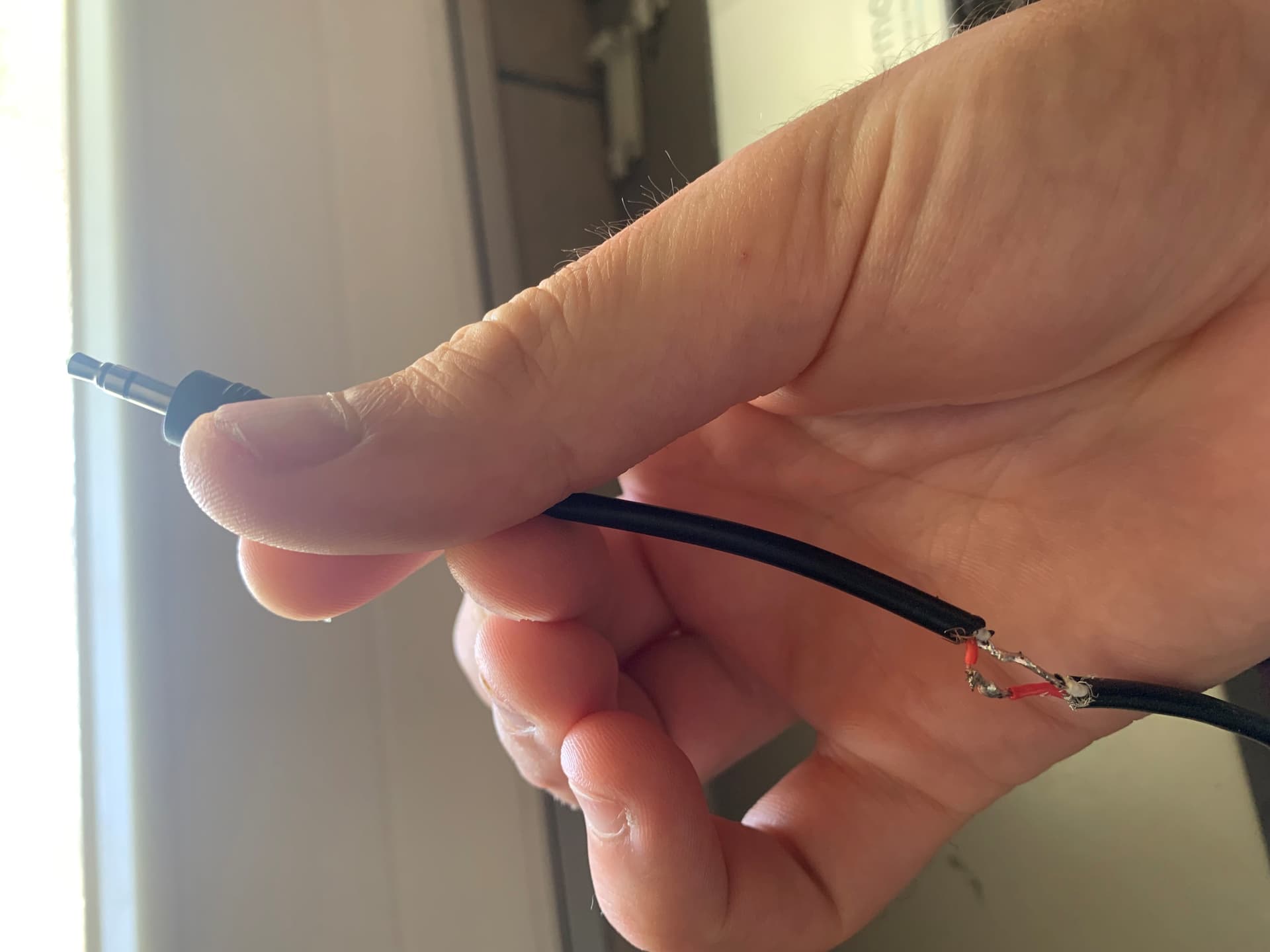
And I am attached to the main power with CT1 P1 E1 and to my solar panels CT2 P2 E2