Hi,
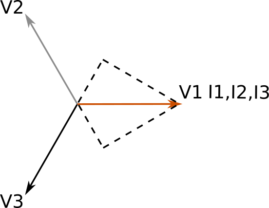
So I’ve updated my EmonTx with the 3-phase firmware. I currently have the 3 CTs monitoring the same line just to make sure the values are different and they are, however the values for CT2 and CT3 are negative despite all 3 CTs are facing the same direction. I haven’t made any changes to the firmware either, so I’m not sure if I missed something in the user guide. A sample of the output can be seen below.
pi@raspberrypi:~/emontx-3phase $ pio device monitor
Warning! `env_default` configuration option in section [platformio] is deprecated and will be removed in the next release! Please use `default_envs` instead
--- Available filters and text transformations: colorize, debug, default, direct, hexlify, log2file, nocontrol, printable, send_on_enter, time
--- More details at http://bit.ly/pio-monitor-filters
--- Miniterm on /dev/ttyUSB0  9600,8,N,1 ---
--- Quit: Ctrl+C | Menu: Ctrl+T | Help: Ctrl+T followed by Ctrl+H ---
ct1:67.98,ct2:-41.89,ct3:-12.93,ct4:0.00,vrms:242.53,t1:300.00,t2:300.00,t3:300.00,t4:300.00,t5:300.00,t6:300.00,pulses:0
ct1:69.12,ct2:-43.32,ct3:-13.63,ct4:0.00,vrms:240.72,t1:300.00,t2:300.00,t3:300.00,t4:300.00,t5:300.00,t6:300.00,pulses:0
ct1:68.54,ct2:-42.42,ct3:-13.33,ct4:0.00,vrms:241.68,t1:300.00,t2:300.00,t3:300.00,t4:300.00,t5:300.00,t6:300.00,pulses:0
ct1:67.72,ct2:-41.96,ct3:-12.79,ct4:0.00,vrms:242.25,t1:300.00,t2:300.00,t3:300.00,t4:300.00,t5:300.00,t6:300.00,pulses:0
ct1:67.79,ct2:-42.08,ct3:-12.65,ct4:0.00,vrms:243.06,t1:300.00,t2:300.00,t3:300.00,t4:300.00,t5:300.00,t6:300.00,pulses:0
ct1:67.90,ct2:-42.34,ct3:-12.60,ct4:0.00,vrms:243.33,t1:300.00,t2:300.00,t3:300.00,t4:300.00,t5:300.00,t6:300.00,pulses:0
ct1:68.04,ct2:-42.35,ct3:-12.78,ct4:0.00,vrms:242.20,t1:300.00,t2:300.00,t3:300.00,t4:300.00,t5:300.00,t6:300.00,pulses:0
ct1:67.95,ct2:-42.38,ct3:-12.80,ct4:0.00,vrms:242.41,t1:300.00,t2:300.00,t3:300.00,t4:300.00,t5:300.00,t6:300.00,pulses:0
ct1:69.40,ct2:-43.66,ct3:-12.97,ct4:0.00,vrms:243.18,t1:300.00,t2:300.00,t3:300.00,t4:300.00,t5:300.00,t6:300.00,pulses:0