I’m just coming back to this forum after years away so very rusty. I have a prototype three phase PV diverter from Robin Emley that has been running successfully for around 6 years. It used to send data to a nanodeRF together with data from an EmonTx. I’ve let my Emoncms.org account lapse and also find that I can’t get my nanodeRF to talk to my home network. I’m now thinking that rather than try to get my nanode working again I should replace it with an EmonBase and use the onboard Emoncms. Should everything communicate as before? Is there anything I should know?
I think everything should work - but you might need some tweaks. What radio frequency are you on? - that’s the first pitfall. The emonBase is only available with a 433 MHz radio, or with no radio (if you need 868 MHz, you can add your own), your Nanode might be either 433 or 868 MHz. (If you’ve forgotten, there are photos of the different radio modules in ‘Learn’.) You’ll also need to check what Robin’s sketch sends and write an entry in emonhub.conf to suit. I can help there if you wish.
Many thanks for your reply - that sounds very promising. Fortunately I’ve already been able to confirm from 2014 correspondence with Robin that everything is on 433 Mhz. A double-check in Learn has echoed this. Can you remind me what emonhub.conf does? I said I was very rusty!
It defines what inputs over the radio (in your case) are accepted and their format - and other things that won’t affect you.
The 3-phase sketches are listed on Robin’s site all have the same radio data packet format, and use the same Node ID and our standard Group:
const int nodeID = 10;
const int networkGroup = 210;

typedef struct {
  int power_L1;
  int power_L2;
  int power_L3;
  int Vrms_L1;
  int Vrms_L2;
  int Vrms_L3;} Tx_struct;
Therefore, you need to delete and replace, or edit, the existing entry (when you get it!) in emonhub.conf You can do this either after you’ve written the emonCMS download to SD card, or in a web browser when it’s running (the latter is easiest).
What you will have for Node 10 is:
[[10]]
    nodename = emontx1
    [[[rx]]]
       names = power1, power2, power3, power4, vrms, temp1, temp2, temp3, temp4, temp5, temp6, pulse
       datacodes = h,h,h,h,h,h,h,h,h,h,h,L
# 26 Bytes
       scales = 1,1,1,1,0.01,0.01,0.01,0.01,0.01,0.01,0.01,1
       units = W,W,W,W,V,C,C,C,C,C,C,p
and what you need is
[[10]]
    nodename = Mk2PVRouter-3phase
    [[[rx]]]
       names = power1, power2, power3, vrms1, vrms2, vrms3
       datacodes = h,h,h,h,h,h
       scales = 1,1,1,1,1,1
       units = W,W,W,V,V,V
This will give you the power in Watts (integer) and the voltage in Volts (also an integer).
That’s awesome thank you. Data is now coming through nicely to my new emonbase from Robin’s kit so I think I’m getting voltage on each phase and import/export on each phase. The bit I forgot to mention is that I also have an old emontx which measures PV generation on each phase. I have no recollection of how that was configured. Any guesses?
How old? Is it a V2? (about the same size as the Nanode, with 1 co-ax ‘power’ and 5 jack sockets, and a 28-pin DIL processor down the middle).
Everything wasn’t quite so standardised in those days, but I can probably make a few guesses.
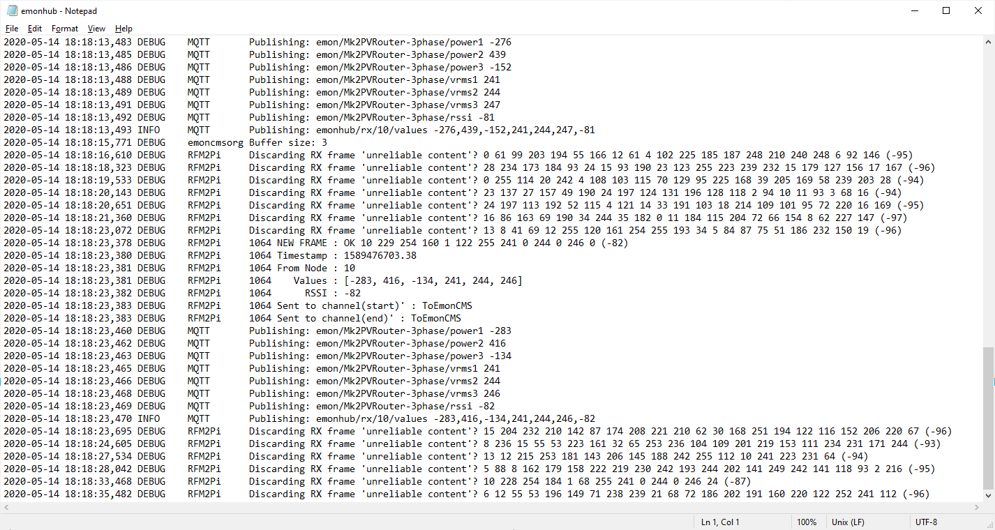
Is it running? If it is, look in your web browser at the emonHub incoming data and grab a screenshot if you can.
At a first guess, that might be a Node 10 too (PROBLEM!) sending 3 powers and voltage (8 bytes, which you’ll see as “10 xx xx yy yy zz zz vv vv (ss)” xx etc being the numbers in bytes printed as decimal  )
)
If I’m right but it’s not Node 10, then chop the rightmost 2 values off the 4 lines above and use that (changing the ‘10’ and the name to suit, of course).
Sorry, I didn’t fully answer your questions. It’s a v3.
What sort of V3? The type should be printed on the pcb, if you can’t see it, there are two basic variants: the V3.2 which has, on the main pcb, a RFµ328, and on that the RFM12B radio module; and then there’s the later V3.4 that has the processor mounted directly on the PCB. Knowing which will narrow the possibilities even more.
I’m afraid that image doesn’t help (and a copy&paste would have been a lot easier to read).
Do you have a programmer? If so, can you connect it, start the emonTx up and note the initial display. That should give you the sketch version, which should give enough information to identify what it’s sending.
It’s v3.2.1 Feb 2014.
Reading the initial display:
Voltage: vemonTx V3 CT1234 Voltage 3 Phase example
OpenEnergyMonitor.org
Node: 9 Freq: 433Mhz Network: 210
I’ve found a sketch in my files entitled “emonTx V3 CT1234 3-phase Voltage example”. It seems to be your sketch V1 dated 7/11/13. I guess this is the one that’s running.
The data it’s generating looks sensible although I’m not sure what’s happening with Current 3 - I think I’ll have to look at the CT which is inside a cabinet:
Voltage: 244.97
Current 1: 5.75 Power 1: -1405.02 VA 1: 1408.74 PF 1: -1.00
Current 2: 5.66 Power 2: -1398.68 VA 2: 1385.77 PF 2: -1.01
Current 3: 0.09 Power 3: 5.78 VA 3: 22.33 PF 3: 0.26
OK, I have found it. First comment - it’s been superseded by the 3-phase PLL sketch. This later one should be more accurate, and I’d advise you to swap to it.
However, if you prefer to stay with the old one, the Node definition you need in emonhub.conf will be
[[9]]
    nodename = emonTx V3 CT1234 Voltage 3 Phase
    [[[rx]]]
       names = power1, power2, power3, power4, Vrms
       datacodes = h,h,h,h,h
       scales = 1,1,1,1,1
       units = W,W,W,W,V
It looks as if CT3 has become unclipped from its cable. If not, the ferrite core might be broken - and that will mean a new c.t. (The low power factor is the clue.)
If you do want to move forwards to the new sketch, it’s at GitHub - openenergymonitor/emontx-3phase: emonTx 'approximate' 3-phase firmware
First, you’ll need to check that you have the RFM69CW radio module in your emonTx - it won’t work with the old RFM12B. There are pictures of the various radio modules here.
If that’s OK, then go through the documentation and set up the options you need. You’ll probably want to disable CT4. I think most of the rest will be OK as they are.
And for emonhub.conf, you’ll need to copy the node definition in the file. You probably want to change it back to Node 9 (but it could stay as Node 11 if you wish - that’s already in emonhub.conf as “emontx2”).
Brilliant. Thank you so much for your help. The emonTx has the RFM12B so looks like I’m stuck with the old sketch. I had to move the emonBase to a point where it would pick up data from the emonTx and PV diverter at the same time. I also plugged the missing CT plug fully into the emonTx board and that fixed the missing input. I’m now getting a full set of data - PV generated on each phase, import/export on each phase and voltage on each phase. The signal strength isn’t brilliant from the emonTx and drops from time to time so I’ll have to do something about the relative positions of the kit and alignment of the aerials. I’m now ready to move on to the feeds.
The aerials - assuming all the items are in roughly the same horizontal plane - should be vertical, pointing up or down doesn’t matter.
The easy way to boost the signal is to provide a ground plane - just a reflective metal surface that provides a mirror image of the aerial. If you search, there’s a thread with videos etc about it.
Also check that you’re not in a dead spot due to multipathing and standing waves. Moving only an inch or so can make a huge difference if that’s the problem.