Doubt in this line of Emon Code "offsetV = ADC_COUNTS>>1"

Could anyone help me in these lines of code, please?

offsetV = ADC_COUNTS>>1;

offsetI = ADC_COUNTS>>1;

I didn’t understand how and why it increments, and also from this line: #define ADC_COUNTS (1<<ADC_BITS)

I also didn’t understand why the 0.55 and 0.45 constants:

startV = analogRead(inPinV); //using the voltage waveform
if ((startV < (ADC_COUNTS0.55)) && (startV > (ADC_COUNTS0.45))) st=true; //check its within range
if ((millis()-start)>timeout) st = true;
}

Any help will be welcome!

I’m no expert on this code, so I stand to be corrected, but I’ll have a stab at it.

That’s giving you the total numeric span of the ADC for your platform. If you’ve got a 10-bit ADC then it’ll be 1024, and 4096 on a 12-bit platform.

It’s not an increment but a divide by 2. So on a 10-bit platform, you’d expect the Vcc/2 mid-rail to return a reading of around 512 and 2048 on a 12-bit platform (subject to component tolerances etc.)

The comments say it’s waiting for a reading somewhere near a zero-crossing. In a perfect world, with infinite sampling bandwidth and perfect components, you’d expect to see ADC_COUNTS * 0.5 at the zero crossing. The 0.45 to 0.55 slop allows for an imperfect world.

2 Likes

@dBC, that’s all absolutely correct.

Thank you very much, I got it
You helped a lot!

Good day everyone. I also didn’t understand the purpose of ‘offsetV = ADC_COUNTS>>1;’ and ‘offsetI = ADC_COUNTS>>1;’, but managed to understand them after finding this thread on google.

In addition, I would like to ask the meaning of additional line. Please let me know if I should open a new thread instead of replying on this one. Thank you.

The first one is related to the following command:

(line 99) lastFilteredV = filteredV; //Used for delay/phase compensation

I noticed that this is the first time ‘filteredV’ and ‘lastFilteredV’ is defined in ‘EmonLib.cpp’. I am still new in arduino. If the arduino runs this line for the first time, will ‘filteredV’ and ‘lastFilteredV’ will be assigned as ‘0’ (zero) by default for the first time?

The second question is related to the following commands:

(line 111) offsetV = offsetV + ((sampleV-offsetV)/1024);
(line 112) filteredV = sampleV - offsetV;
(line 113) offsetI = offsetI + ((sampleI-offsetI)/1024);
(line 114) filteredI = sampleI - offsetI;

I have no idea how this digital filter filter works. May I know what is the purpose of ‘((sampleV-offsetV)/1024)’ in line 111? After that, may I know why ‘((sampleV-offsetV)/1024)’ have to be added to ‘offsetV’ (also in line 111)? Then, may I know why we have to perform ‘sampleV - offsetV’ (in line 112), which I believe is also similar to ‘sampleV - (offsetV + ((sampleV-offsetV)/1024))’ (the combination of line 111 and 112). Please let me know if there is any related material available related to this.

The third question is related to the following commands:

(line 131) phaseShiftedV = lastFilteredV + PHASECAL * (filteredV - lastFilteredV);
(line 136) instP = phaseShiftedV * filteredI;

I am also have no idea how does this part works. If anyone have reading material related to this, I would like to ask you to let me read it. One more thing, if it is the first time the arduino is going to run this loop, the value for ‘lastFilteredV’ will be ‘0’ (zero) by default, right?

The fourth question is related to the following commands:

(line 158) double V_RATIO = VCAL *((SupplyVoltage/1000.0) / (ADC_COUNTS));
(line 159) Vrms = V_RATIO * sqrt(sumV / numberOfSamples);

(line 161) double I_RATIO = ICAL *((SupplyVoltage/1000.0) / (ADC_COUNTS));
(line 162) Irms = I_RATIO * sqrt(sumI / numberOfSamples);

May I know why the SupplyVoltage hac to be divided by 1000.0 in line 158 and line 159?

I think that is the question that I would like to ask at this moment. Thank you very much and have a nice day.

Yes. But so what? All it means is the very first point in a continuous process that runs for months will be not be “corrected” for the transformer phase errors / timing error.

I answered exactly this question only 2 days ago. Digital low pass filter for DC offset removal - #2 by Robert.Wall

This is covered in Resources > Building Blocks - look for “phasecal”.

Follow the code back to see where SupplyVoltage comes from, and check the units.

Dear Mr. Robert Wall,

Thank you very much for your reply. I need some time to digest your reply for question 2 until 4. I will be back once I’m done. :smile:

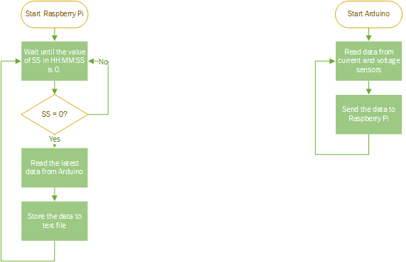
Instead of running the code in a continuous process that runs for months as you said, I am planning to do something different. I plan to link the Arduino with Raspberry Pi. The Raspberry Pi will keep on reading the time from the clock (in HH:MM:SS format) and send a signal to Arduino once the value of SS = 0. Meanwhile, the Arduino is not running anything while waiting for ththe signal from Raspberry Pi. Once the Arduino receives the signal from Raspberry Pi, then the Arduino will execute the following command in voltage_and_current.ino file for ONLY ONE LOOP:

(line 16) emon1.calcVI(20,2000); // Calculate all. No.of half wavelengths (crossings), time-out
(line 17) emon1.serialprint(); // Print out all variables (realpower, apparent power, Vrms, Irms, power factor)
(line 18)
(line 19) float realPower = emon1.realPower; //extract Real Power into variable
(line 20) float apparentPower = emon1.apparentPower; //extract Apparent Power into variable
(line 21) float powerFActor = emon1.powerFactor; //extract Power Factor into Variable
(line 22) float supplyVoltage = emon1.Vrms; //extract Vrms into Variable
(line 23) float Irms = emon1.Irms; //extract Irms into Variable

This is summarised in the flowchart below:

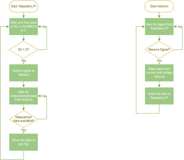
However, If this method will make the result becomes inaccurate because the code above should be run continuously for months as you said, then I will modify the Arduiono code so that the loop runs continuously. Meanwhile, the Raspberry Pi will keep on reading the time from the clock (in HH:MM:SS format) but store the latest data obtained from Arduino once the value of SS = 0. This is summarised in the flowchart below:

Noted. Will discuss about this matter on the following link from now onward.

Already read the link. I will also use resistive load (kettle etc.) and andjust the PHASECAL value (using try and error method?) so that real power = apparent power, as stated in the link below:
Calibration Procedure

Noted. I have checked the following code in the EmonLib.cpp file:

(line 68) #if defined emonTxV3
(line 69) int SupplyVoltage=3300;
(line 70) #else
(line 71) int SupplyVoltage = readVcc();
(line 72) #endif

At first I thought readVcc() will give the value of 5 (for 5 volts), but after reading the value 3300 in line 69, I concluded that readVcc() should give the value of 5000 (for 5 volts).

Thank you.

But the consideration is still much the same. You are going to have the first point in 1000 cycles (20 seconds), or a little more than 50000 samples, wrong by a small amount (bear in mind that this first point is a small value anyway as it is as close as possible to the zero crossing). Realistically, what difference will it make?

And when you read the code inside readVcc(), you saw that it is indeed giving the result in millivolts. It means an integer can be used, integer maths is generally faster than floating point. We use integers wherever we can because like to keep the maths operations inside the loop as fast as possible in order to have as many samples per cycle as possible.

All right, understood. as a beginning, I will choose the simplest implementation between the 2 flowcharts (and try the other one if I have extra time) to compare the result).

Noted. I am still a newbie in Arduino and will spend more time to understand the the code inside readVcc().

Thank you.

I didn’t understand below line:
phaseShiftedV = lastFilteredV + PHASECAL * (filteredV - lastFilteredV);

It is a low pass software filter.

Can you please send the link where you found this example?

Welcome @Sabeeh_Alam to OEM.

It has been over 5 years sine we have seen Foxfisal, so I would not expect a reply.