2.8V is the lower end of the range for these boards but should still work okay.
The current sensing isn’t implemented, so don’t buy anything for that.
2.8V is the lower end of the range for these boards but should still work okay.
The current sensing isn’t implemented, so don’t buy anything for that.
Thanks for all your help @stuart
In software or hardware? I’m pretty good with software and could add that in…
Both!
No idea - you need to give us more information, are you using the BMS controller PCB ?
What does the output look like on the DEBUG pins? (connect to a serial port 115200,8,N,1)
I way prefer this !
Nope - they are tiny components though!
Thanks yip, I know they are small, I have 50 boards on their way, so I’ll have to do my best to try fix those, fortunately it’s on 2 components per board and considering we will be soldering the the ATTINY anyway, it is what it is, but at least as mentioned hear this community has enough interest and movement that it was picked up early enough to not effect to many people.
Again welcome Stuart for all you effort.
Hello all and specifically Stuart,
I’m in the process of installing a 150 Ah 24V (8 LiFePo4 cells) battery and a 1.2 kW solar panel array.
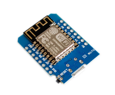
I’ve built 9 modules so far, but unfortunately I couldn’t get all the components from LCSC due to stock shortage. But I’m only missing 2, so it should be relatively easy to find the last ones.
I have a question for Stuart.
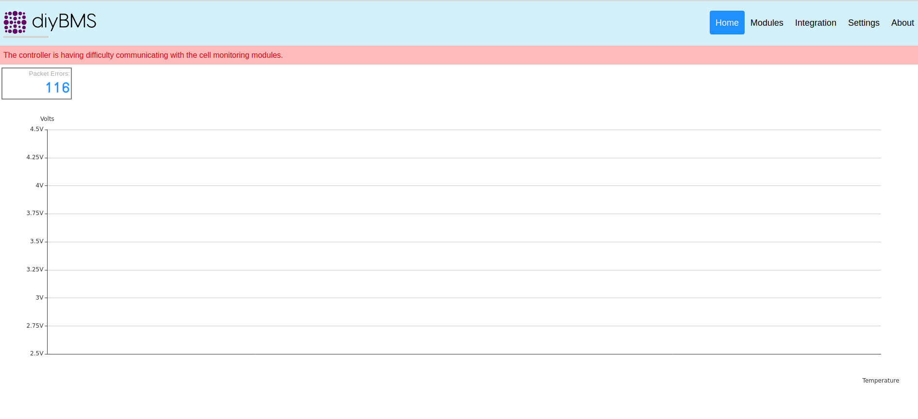
Is this system suitable for a battery of this size? It is my understanding that the function of this BMS is to control, at least, over-voltage and monitor cell voltages. But I wonder how the system deals with under-voltages of cells?
I see no way to shut off the discharge current of the solar system from these modules.
So I assume that they only provide overvoltage protection with the 1A load dump. Is this correct?
As I said, I have already decided to implement it either way, and have built 9 modules already but waiting for the WeMos in the mail.
Yes the BMS is suitable for the battery size you are building.
The BMS itself doesn’t switch on and off the loads or chargers. It can control a relay board which can be used to drive high power contactors to switch the loads on and off.
Aah, yes that makes sense.
I’m driving 150A max, so it will be some big relays, I think a multi-thyristor/MOSFET solution would be worth considering. My inverter will cut off current when the overall battery voltage gets to a specified point and it is powered from the battery, so if an external BMS cuts power, it cuts power to the inverter as well and the builtin charger. The model is MPPSolar MSXE.
Maybe it has an external input that will make it show down. I’ll check the manual.
A contactor can handle many hundreds of amps
Hi,
Is there any way I can order Preassembled module, if yes, please let me know how can I order.
Thanks in advance
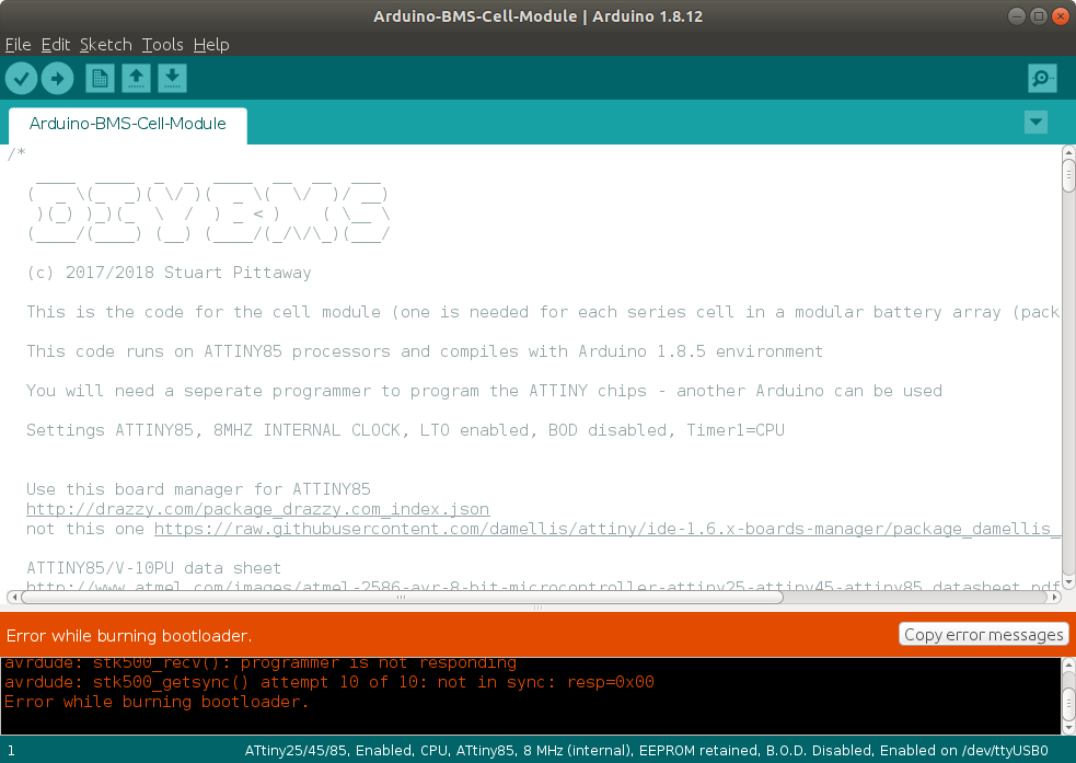
I’ve been trying to get started with my boards from jclpcb. I’ve soldered on the attiny chip and the headers. I’m now trying to program it using Adam Welch’s Video as a guide. I get to the point of burning the bootloader but it fails. Can anyone give me some idea what’s wrong? Here is a picture:
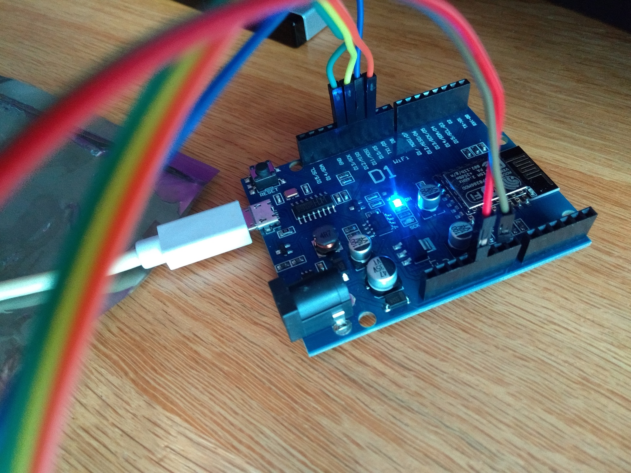
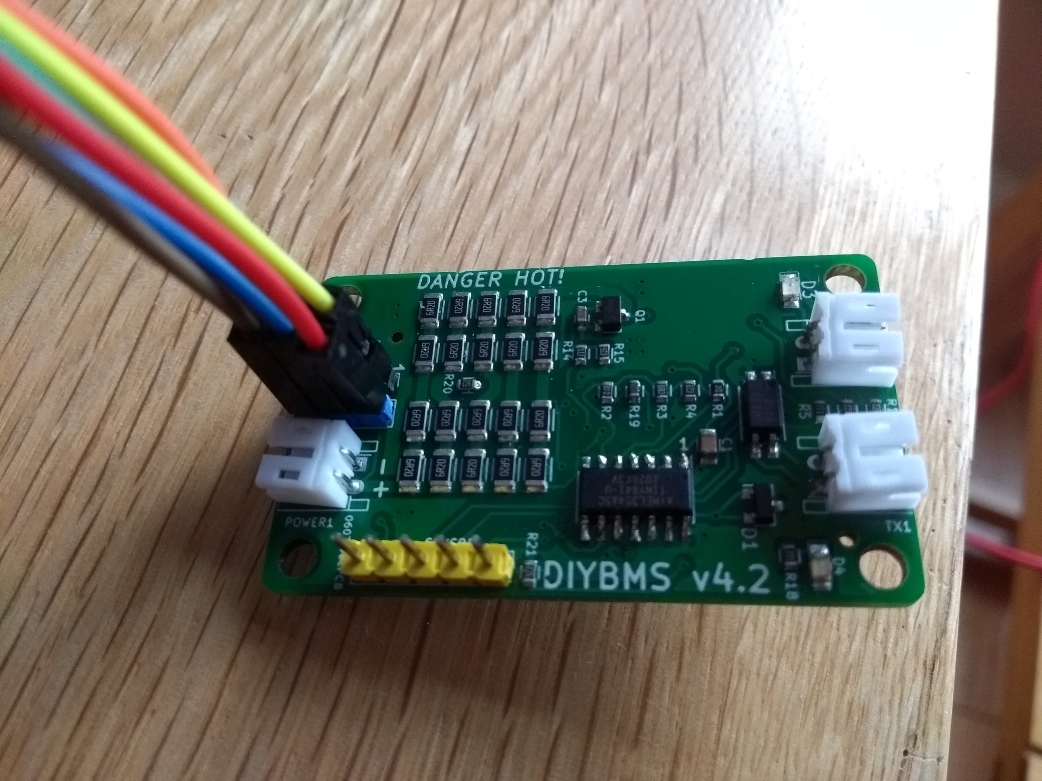
Is my attiny chip the right way round, it’s hard to see the marker for pin 1? Here some pictures of my setup:
Don’t use Arduino IDE to program the boards.
Use Vscode and platformio.
Yes pin 1 is correctly aligned to the pin 1 label on the board
OK, thanks.
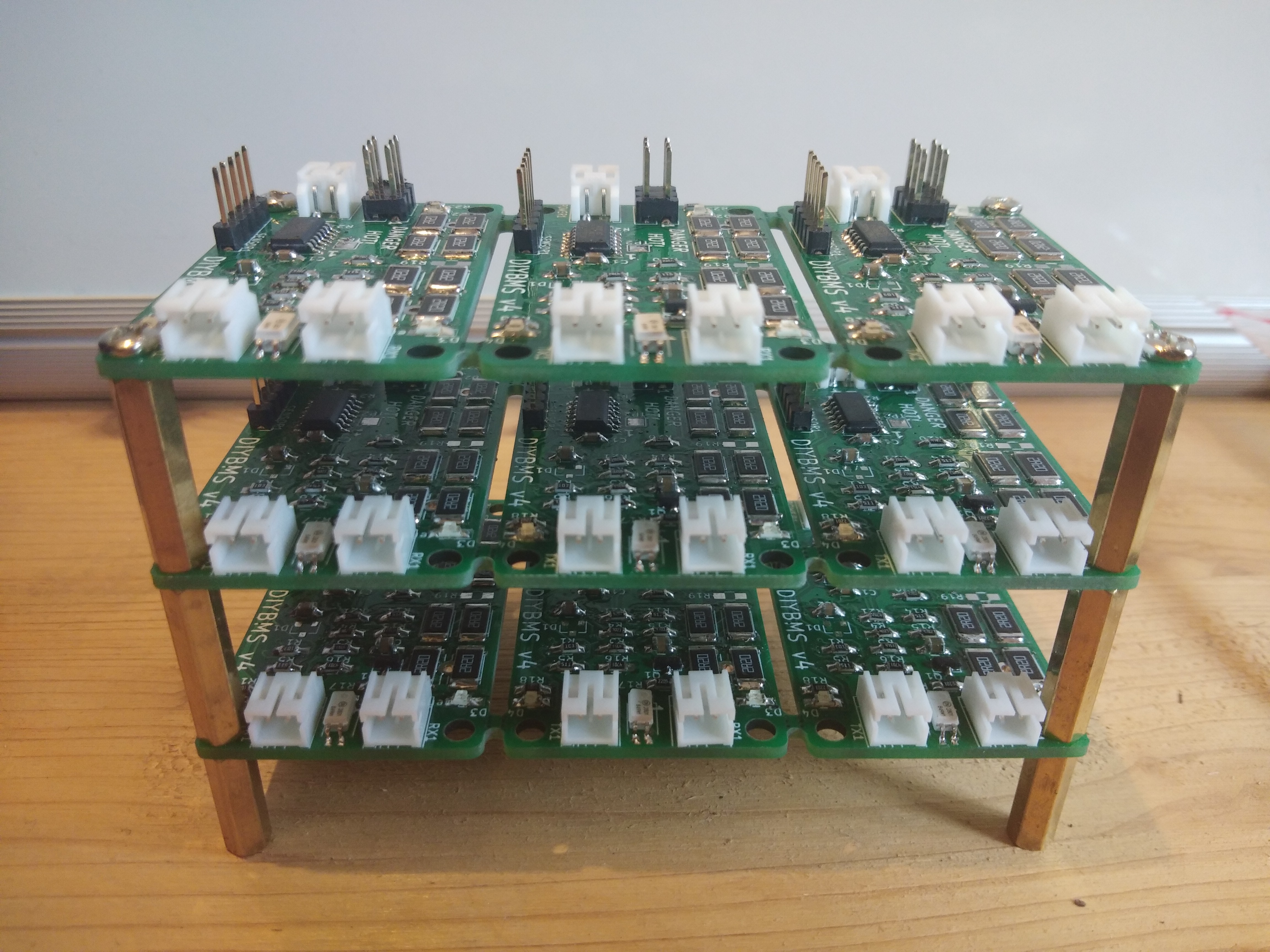
is it possible to program the ATTINY Cell Modules with Arduino mega 2560.