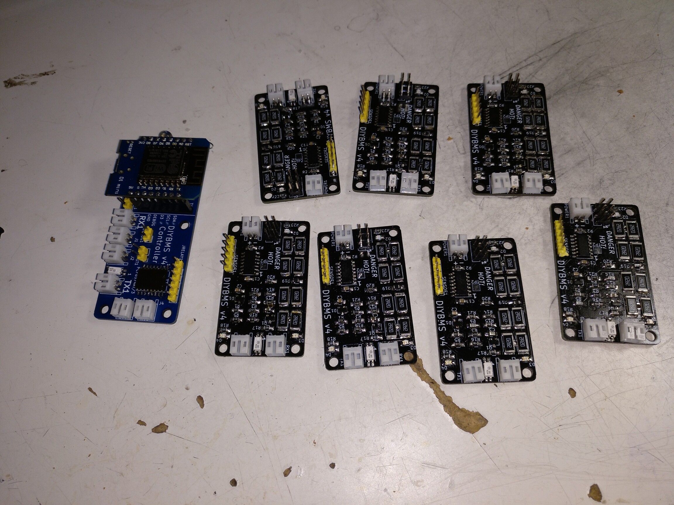
I just ordered 50 of the balance boards and 5 of the ESP boards. I should have more then enough for future projects. I ordered them bare and I will probably try the toaster oven reflow to assemble them.
Now I just have to order the components.
I just ordered 50 of the balance boards and 5 of the ESP boards. I should have more then enough for future projects. I ordered them bare and I will probably try the toaster oven reflow to assemble them.
Now I just have to order the components.
Did you order the stencil as well?
I ordered all of my “extra” parts from DigiKey since they had everything, I couldn’t find a couple parts on Mouser but that is also a great place to find most parts. If you are in the US you can also opt for USPS Priority Mail delivery as a really inexpensive shipping method compared to FedEx/UPS options and as a bonus it is pretty fast!
I did not order the stencil, I figured I would probably make a bigger mess with it. I will try with the solder paste in the syringe.
I found that the parts on LCSC were far cheaper, except for the ATiny micro-controller. I had to find a substitute for some of the parts that were out of stock such as the thermistors. It was about $42 for all the components except for the ATiny from LCSC and about $32 for 35 ATinys from DigiKey.
I didn’t order the stencil either and used solder paste for the first time ever on this project, was actually easier than I thought… It took longer to sort all the components than to paste and place. Just waiting for connectors to finish things up but controller programmed via wemos and balance boards programmed with an uno with no issues…
@stuart can I use this as replacement for EL3H7(B)(TA)-G?
https://www.evelta.com/search.php?search_query=Optocoupler+
Or
Probably - it looks like the correct size, so if you can get hold of one try it. I’ve used 3 different types of optocoupler so far and they all worked okay, the circuit isn’t very sensitive to them as its only used for low speed serial communications.
They are not very difficult to build just time consuming if you are doing a few boards, definately easier with solder paste and oven.
Thanks Neil, its not really my design I’m just following in the footsteps of other projects that seem to work well.
It shouldn’t be difficult to use the same code on both the controller and modules to support a different voltage range or features, I’d recommend trying to keep the same CPU/controller if you can so we can then both benefit from a common code base.
Happy to take a look at anything you suggest/design.
This is a great project. Thank Stuart for your great work. You advised me on Facebook to use a real BMS for my powerwall instead of a cheap one from China. Well, that’s what I’m going to do now 
I have now also ordered the boards. I used the jlcpcb_assembly branch and ordered them from jlcpcb. I will order the attiny separately. I also ordered the board for the controller, but without the assembly.
I am a beginner in SMD soldering. Can someone give me the LCSC part numbers I need for the controller?
But this is the right attiny or? https://www.digikey.de/product-detail/de/ATTINY841-SSUR/ATTINY841-SSURCT-ND/4437442/?itemSeq=313738481
Thanks a lot
I’d suggest sort all parts and add all of one component and then move to the next. In my case I did all opto-couplers for all boards, then the ATTiny for all boards and then connectors. By doing this you can quickly get all boards prepped (or in my case soldered).
This is the one I ordered: ATTINY841-SSU Microchip Technology | Integrated Circuits (ICs) | DigiKey
I believe they are in the xslt file in the repository. There aren’t too many parts for the controller thankfully.
It will probably be fine, but note the warning above about this branch being experimental !!
Hi atanisoft,
in the Excel file are only the parts for the cell modules. (CellModules_LCSC_BillOfMaterials.xlsx) or do you mean another file?
@stuart I hope so too. If a component does not work properly I can replace it later. The design of the board will not change that fast. I will read here in the next weeks and follow the Github Branch. If there are changes in the components I will surely ask here again
Just check using a multimeter between the battery + and - that there are NO short circuits before powering on for the first time!
You are right, I forgot that the controller had it’s own file:
https://github.com/stuartpittaway/diyBMSv4/blob/master/ESPControllerCircuit/ESPControllerCircuit.csv
Is this a 2A discharge or are the R changing to a smaller package and R value?
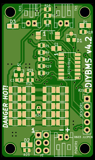
Something else that might make sense is adding a note on the SENSOR1 connector as to what the pins are for so we don’t need to refer to the schematic etc. I know pins 1,2 are for the external temp thermistor but I forget now what the others are.
Also on the ICSP if you shift D2/R23 to the left you can add the pinout on the silkscreen as reference for those that are not using the USB ASP and instead using jumpers.
Same discharge as the original v4 just using different R values.
Good idea on the ICSP header, although I don’t actually solder in the header pins and use a POGO pin adapter instead - saves parts and the need for manual soldering.
do you have a link to the POGO adapter? I’ve only used the pin headers so far and don’t mind that but having a POGO option might be nice for other boards…