It seems some screens already have the resistor on the board, and others don’t. That resistor is just a current limiter. It may be worth checking what current you are now pulling, you don’t want to burn out the TFT backlight.
you are absolutely right i have a 3R9 resistor at the led input on the tft itself, on the TCA9534A i think the maximum is 50ma, recomended is 25ma and my tft led conected directly to a 3.3v power supply will use 57ma of energy, so maybe a resistor to bring it to 25ma would be the best.
I think the tft itself is supposed to be conected directly to 3.3v if you don’t want to drive in externally.
I am looking to get a new version controller and shunt, but doing a single order and shipping to South Africa is prohibitive, if anyone is will to do a group buy and then once they receive the components can ship to me, please contact me.
Hey @stuart
Just checking, does the DiYBMS work with LiFe cell chemistry. I was hoping to use it in 60s configuration ? would that be possible ? What is the max voltage for this chemistry that the BMS can monitor.
Have you seen this:
awesome
Hi @stuart ,
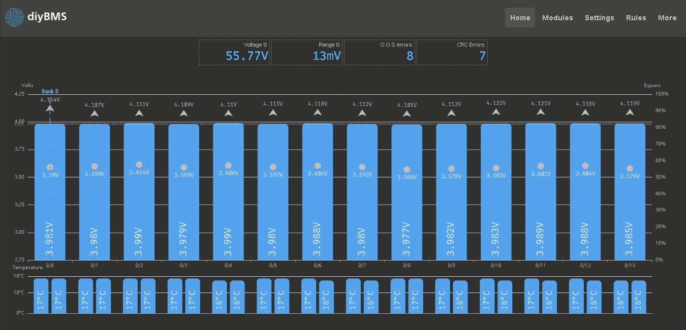
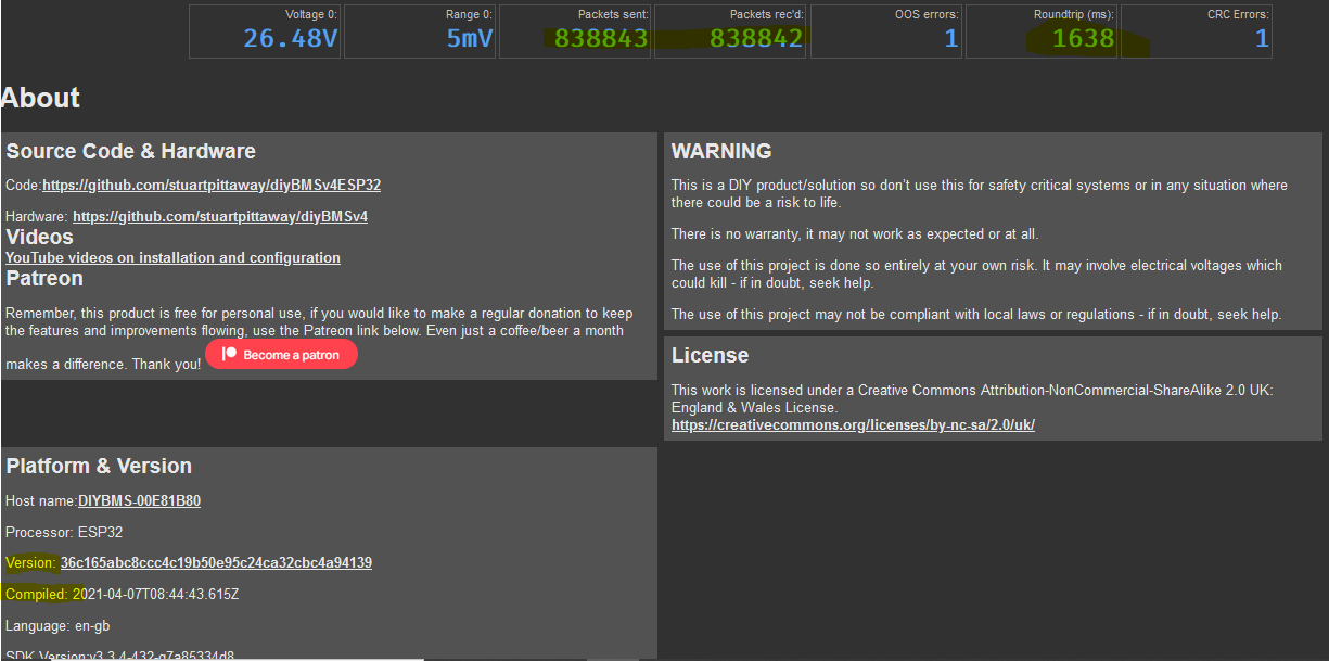
Finally I have finished the first string of my battery and put everything in operation. It works alredy for a couple of weeks without issues, however OOS and CRC errors counters are constantly counting up. It does not affect the functionality, but still not a perfect situation. Can you please advice me how to fix it?
I have reset the counters and after approximately 30 minutes made those screenshots.
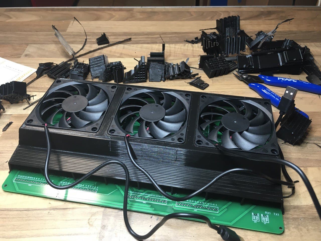
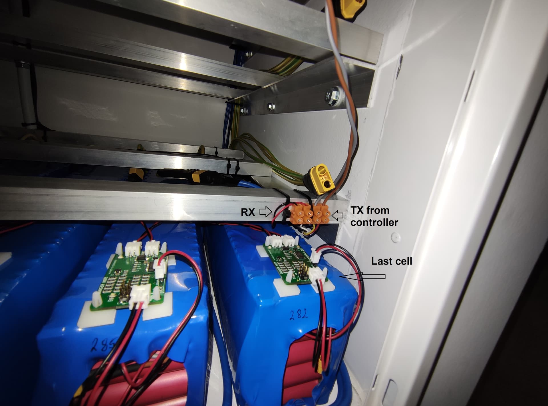
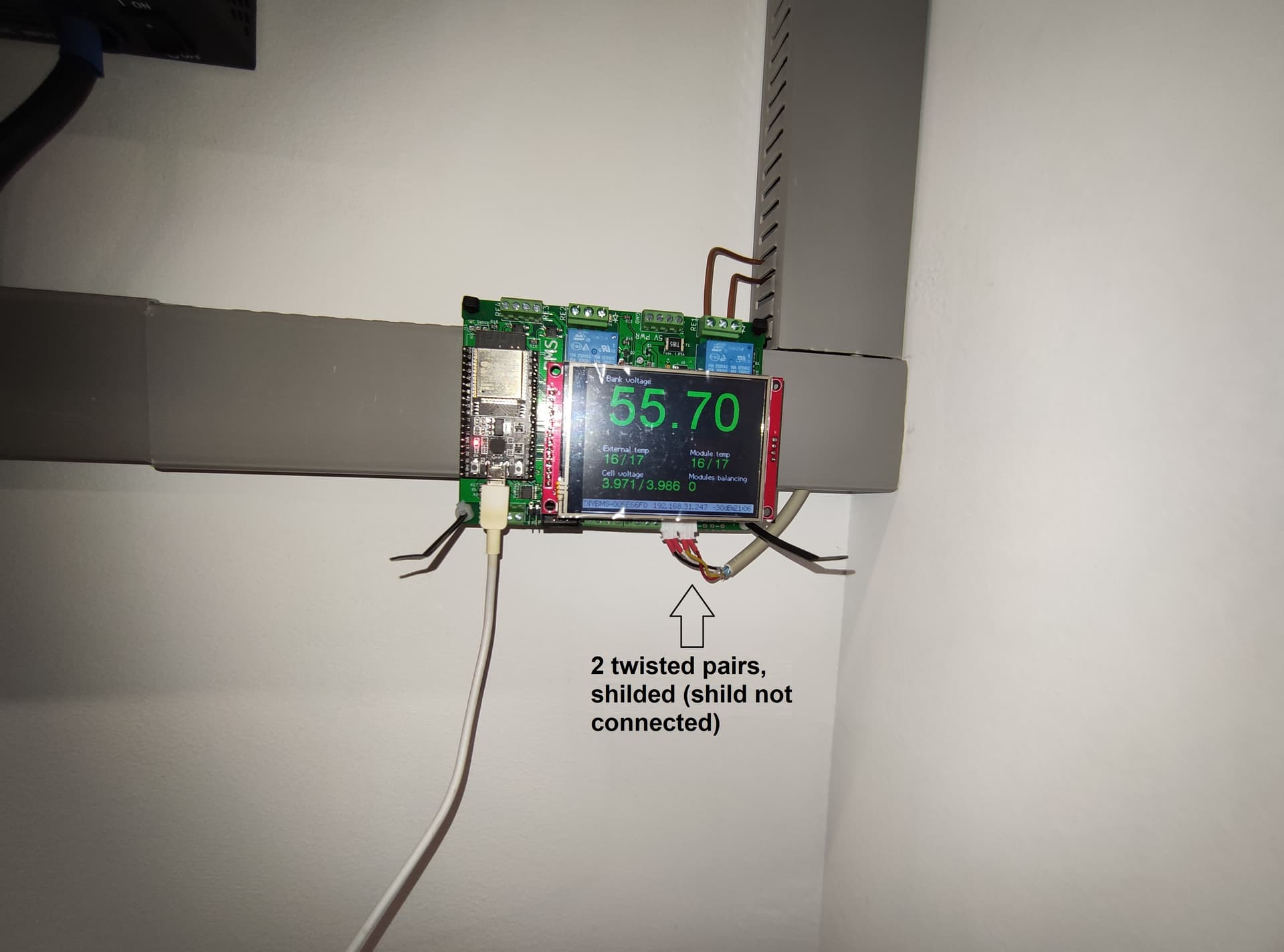
And here is my build

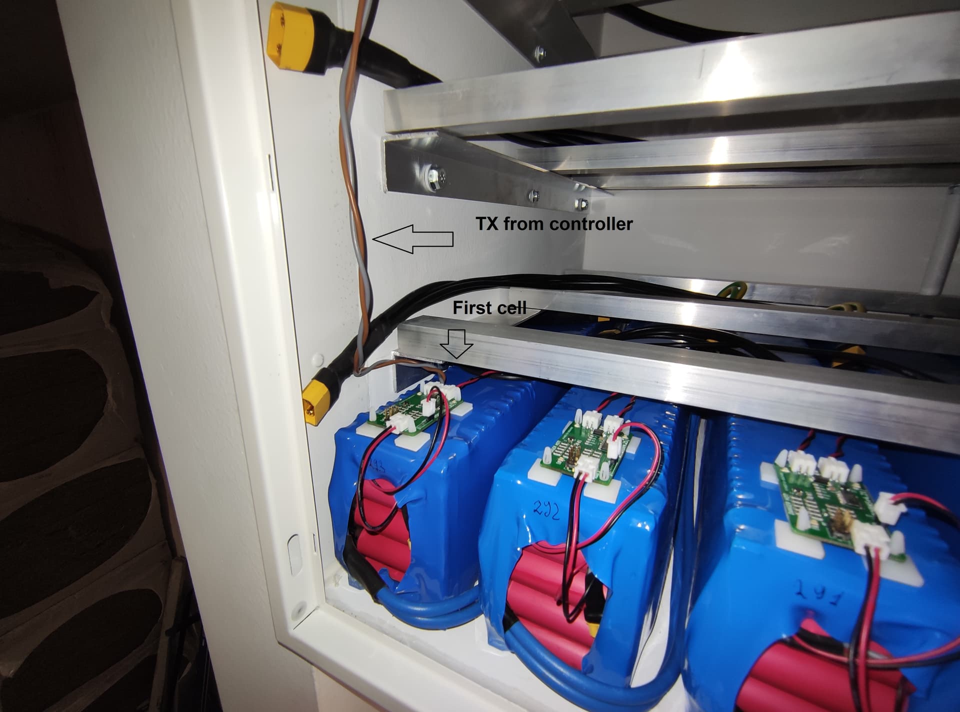
The cable from controller to battery compartment is no longer than 2 meters. It is, however, in the same cable trace with power cable from inverters to the distribution box, and at the top partly in the same bundle with battery cables.
Many thanks in advance!
1 Like
Ok, the 2m length of cable could be an issue.
Is that twisted pair cable? If not try that.
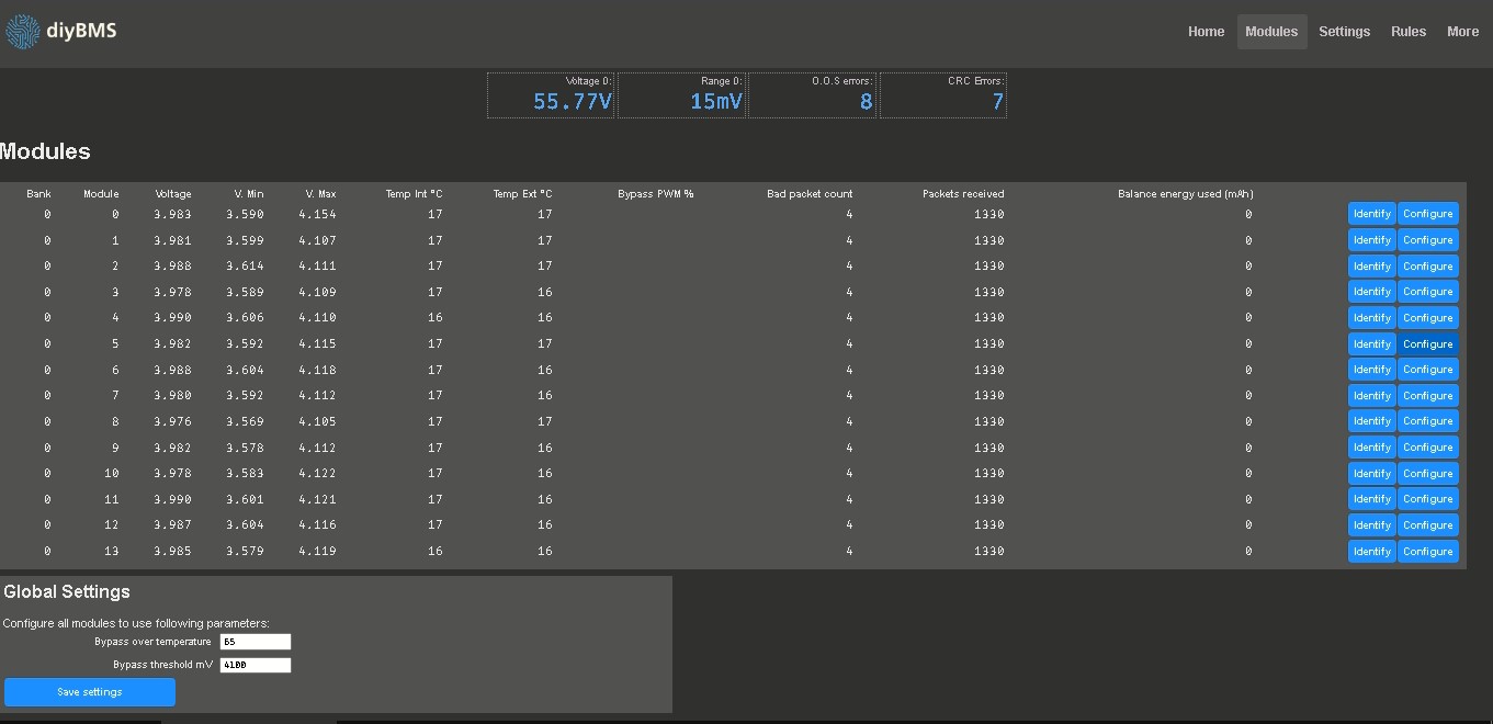
If you take a look at the module page, you should be able to see the packet count per module. They should all be the same value.
Upload a screen shot if they are not.
1 Like
Thank you for the fast reply.
Yes, it is a 0.8x2x2 cable (2 twisted pairs in the same shield, 0,8 mm2 coper), approximately 2m from controller to the battery compartment and then within a battery compartment it is changed to a 1mm2 coper twisted wires on tx side, approximately 1,5m which goes to the 1st cell, then daisy chain with like 12-15 cm patch cables (all good twisted), and from the last cell back to the controller through the 2nd pair of the 0.8x2x2 cable. See the photos on the post above.
The screenshot is already uploaded in the post above and yes, it is always the same number for both Bad packet count and Packets received.
Ok, if all the packet counts on the modules are the same it means the signal is getting corruption from the last module to the controller.
Can you make this cable shorter?
1 Like
VERY nice!
2 Likes
Very clean build.
I wish my temperatures were so consistent.
What version of code are you running - i’m presently ~1 version behind the latest but it provides more on screen valuable diagnostics.
1 Like
At least for an experiment - yes. I will do the test and share the results. But the Idea was to have batteries in the metal, “incombustible” compartment and everything else: inverters, charge controllers, BMS controllers - below with an easy excess. It means that at least 1 - 1,5 m communication cable would be necessary. What are exactly the limitations for cable length from the controller to the first/last cell module?
Thanks
The cells are never at stress, so cell temperatures are always the same as ambient temperature. It is a 140p14s string, and it is protected with a 125A circuit breaker, so never more the 0.9A per cell. And as you see on the photo, there is still place for 3 more strings, which would be soon installed.
the version from 2021-09-02
The diagnostic is still there just below the graph rather than above (running out of room!)
Unfortunately the answer is “it depends”.
The local environment, EMI and the make/model of inverters and chargers make a big difference.
You may also get improved results using a ferrite ring - worth a try if you have one lying around.
Thank you for the recommendations . I will do some experiments on weekend.
By the way, overnight the error counters: oos and crc reached the value of 124 and 118 respectively and additionally there was 1 ignored request. Bad packet count for all cells had the same value - 69. And all this without charging, and only around 300W of discharging, so no significant current flow.
Those numbers are still not that high, although ideally would be lower.
1 Like
I see on your photo, you have
“2 twisted pairs, shilded (shild not connected)”
Does that mean the shield is not connected anywhere? If the shield is not connected to earth somewhere, then it will not help to reduce interference. But you must connect one end only, otherwise currents might flow and make things worse.
keep comunication cables away from power cables.
don’t use twisted pairs from the same cable, use 2 different cables and better with only 2 wires.
If using a shield conect it to the rx side on the negative terminal.
If using a dc-dc to power the controller, try using a phone charger if it gets better maybe you need a isolated dc-dc.