Would the " LM4040AIM3-2.0/NOPB" be a drop in replacement for D1 “LM4040BIM3-2.0/NOPB” for the reference voltage?
@stuart Thankyou for creating such a great device. i was looking at a way of monitoring my nissan leaf cells over wifi, only devices i could find were bluetooth or stupidly expensive (and also buggy for a finished product)
i have successfully made 28 of the cell monitors
i was wondering if i could attached 2 of the boards to one cell to give it 2A discharge running them in 14s 2p would it work this way?
thanks
also would you mind if i offer a service for brits/europe for premade tested and configured units?, i would send a couple of beer tokens your way per set sold if this is allowed thought id ask first to check 
thanks once again
Hi Gareth, unfortunately this is against the terms of the licence for commercial reselling, but I’m glad you got 28 modules working well.
There is a post further up this list with a redesign including Nissan Leaf cell modules.
Yes although this is an expensive part in the “A” type - perhaps try the “D” variant instead?
That’s difficult as I won’t know how many modules each purchaser would need, so unable to determine the quantities!
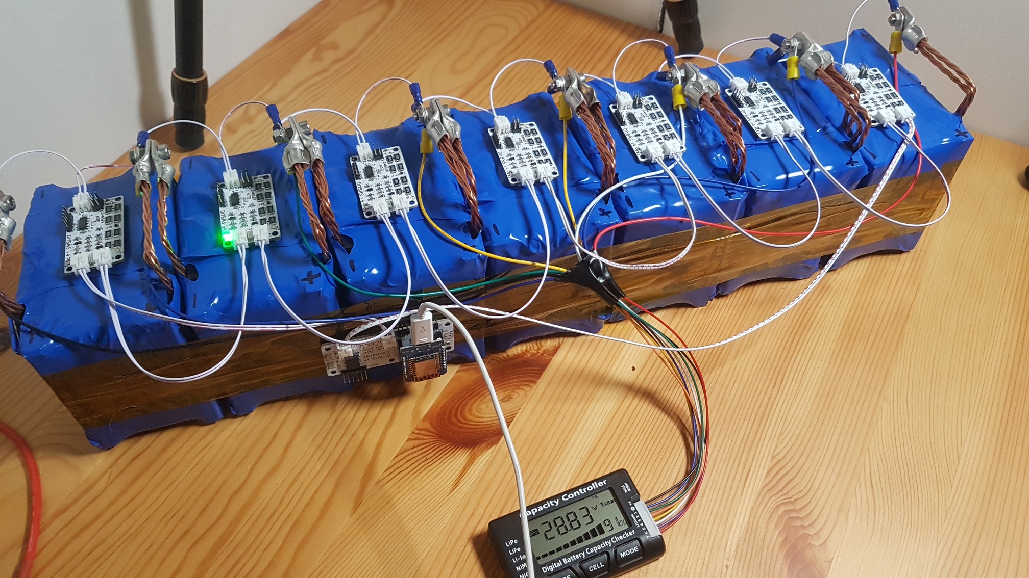
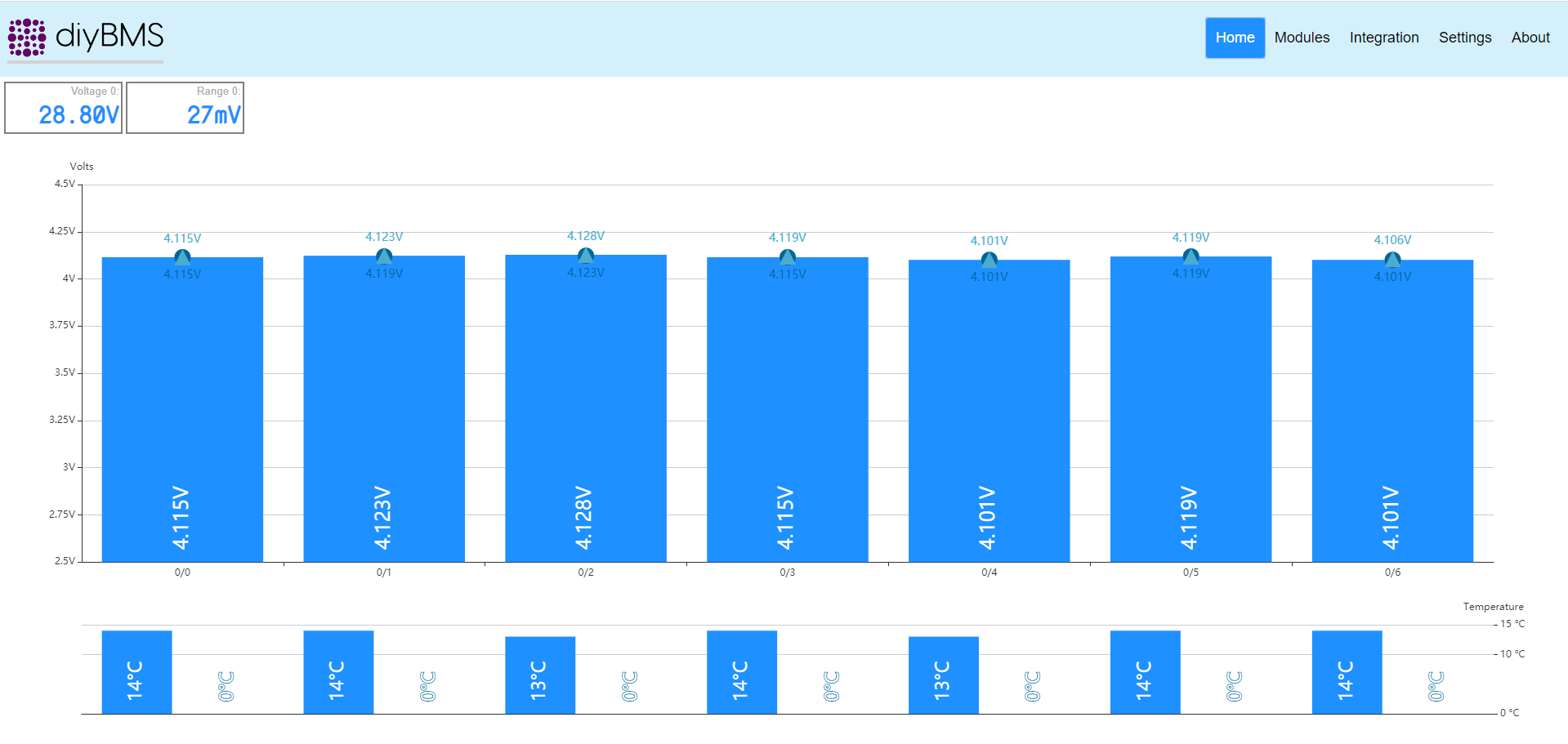
I am able to report the diyBMS-Leaf functions as expected. I have a working stack of 7 - Nissan Leaf cells using 7 custom BMS modules.
I have included a link to a video showing stack in operation.
Each module connects to the next in series via a custom 4-pin cable built with very flexible silicon wires. The crimping tool was $12.
https://drive.google.com/file/d/1HWYfil_fstfz0RvEbjMsthRiiVtsacw5/view?usp=sharing
Warning:: it is a huge file, 50+meg.
I added an image as the video is a bit fuzzy.
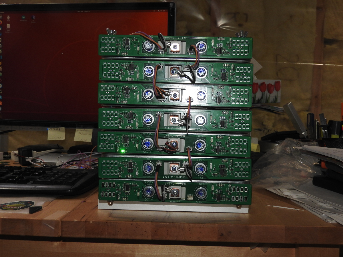
There is still work to be done on the pcb before version 1.00
6 Likes
Yes, this is the solution. Without an internet connection on the ESP boot, the ESP is hanging up.
I’ve connected a mobile WLAN hotspot via Smartphone to the router, so I can usw the DIYBMS now in a off-grid area without internet connection!
I do not have a cable/interface to check the BMS controller report at my powerwall (only in the electronic lab). So I have no reports…
Now, Grafana/Influx is working aswell!
Thanks!
@stuart I wouldn’t expect you to know how much we each need but you do know what is needed per board. Is there a parts list needed for each board on github? Otherwise that would be good to know for the spreadsheet and then we can just multiply as needed.
Thanks!
Yes there is a BOM and CPL files in GITHUB for this purpose.
https://github.com/stuartpittaway/diyBMSv4/blob/Version4.2/Circuit/v4_bom_jlc.csv
1 Like
Thats to be expected with the current build/code. I’ve had a request to allow the controller to work without connecting to a WIFI hotspot/router for use on a boat, that should be easy enough to do.
1 Like
This is brilliant, well done.
no problem, did you see my part about using 2 of these modules per cell to see if it would run 2a discharge if used in parallel?
also seem to be having a problem with the module controller reverting back to 4100mv and 70c, i change it to 4000 and 75c click save and then a few hours later its gone back to 70c and 4100mv
anyone else having this issue?
My first post, though I’ve been following for a long time. I’m about to order 30 of the 4.2 boards and I’ve not done anything with JLCPCB before. Am I correct in understanding from the quote above that if I upload the Gerber files and select the SMT Assembly option that JLCPCB will mount all the components on the boards for me (except for the ATTINY chip and the JST sockets)? Do I have to upload some kind of component list for them to do this or is it somehow included in the Gerber file?
OK, I see you have to add the two files for the components in the next step. Do the boards come ready cut individually or do they come as a board of several boards that you have to cut up yourself (if you see what I mean)?
they come seperatly and stuck together in a line with masking tape
Great thanks for that. I can’t seem to find a BOM and CPL file for the controller board, are there any? Also, I’ve been looking through farnell to order the JST connectors but there are so many to pick from I’m not sure which to get. Order code 9491902 seems to look right but I don’t want to order the wrong bits, can someone (who has ordered from farnell) confirm? Thanks.
I ordered the wrong pcf8574at. I ordered pcf8574t. I know Stuart said you can change address in code. Can someone point me in right direction ? Or should I order the correct one. Thanks
Finally got my test pack (7S30P) all finished! Everything seems to be working correctly… now its time to do some testing
4 Likes
Line 88 of main.cpp of the controller code.
//PCF8574P has an i2c address of 0x38 instead of the normal 0x20
PCF857x pcf8574(0x38, &Wire);
Thanks Tyson I found . Works great !