Same discharge as the original v4 just using different R values.
Good idea on the ICSP header, although I don’t actually solder in the header pins and use a POGO pin adapter instead - saves parts and the need for manual soldering.
Same discharge as the original v4 just using different R values.
Good idea on the ICSP header, although I don’t actually solder in the header pins and use a POGO pin adapter instead - saves parts and the need for manual soldering.
do you have a link to the POGO adapter? I’ve only used the pin headers so far and don’t mind that but having a POGO option might be nice for other boards…
Thanks. I’ve seen this list, but there are no LCSC part numbers on it. I just don’t want to order the wrong things, can someone give me the right part numbers?
R1: C269734
R2,R4,R5: C269746
R3: C269730
RX1, TX1: same as modules (not available on LCSC)
DEBUG1: C124375
JRELAY1: C37208
For DEBU1 and RELAY1 you can really use any break away pin header or socket. They are standard 2.54mm (0.1 in) pitch.
Remember that due to the minimum order quantity from lcsc for the balance board components you likely have the majority of the parts already. I believe Stuart made mention to this back in July (I found the post see below). And don’t forget a wemos mini d1
Blockquote
Quoted from Stuart in July
The list is in the file https://github.com/stuartpittaway/diyBMSv4/blob/master/ESPControllerCircuit/ESPControllerCircuit.csv
If you have ordered the BOM for the modules then you will already have most of the parts, like resistors and the JST connectors and also the optocoupler.
What you will need are:
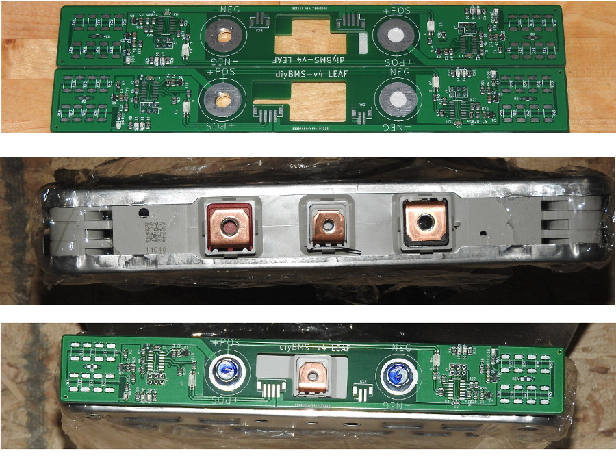
For those interested in a version of the diyBMS-v4 for the Nissan Leaf cells I have the first version of the boards. Of course I missed a few parts, power resistors and JST connectors, but they look good. Once the remaining parts arrive and I build up a few boards I will see whether the magic smoke escapes from the boards. If all goes well I will have a pair of batteries giving me 7kwh running on Stuart’s diyBMS system.
If the shop remains smoke free I will make the files available to Stuart.
That is an awesome looking dual board. I’m guessing that you are using SMT JST connectors and you only have one RX and one TX on there with one ATTiny sending to the second ATTiny directly on the PCB?
Yes, as a dual board you have direct com between the two aTTiny chips. The 4pin connector has 2 connections to the exposed tie point and a TX pair going to the next in the string. The controller will feed the first board and listen on the last in the chain.
Custom cabling but it won’t break the bank. Only 2 JST connectors vs 6 JST for 2 standard boards
Cables are cheap compared to the rest of the setup ![]() I can’t wait to see how it looks when you have a string of them. I know at least one person who is doing a leaf wall around 120kWh (it’s a huge setup!)
I can’t wait to see how it looks when you have a string of them. I know at least one person who is doing a leaf wall around 120kWh (it’s a huge setup!)
Thank you!
On the Cellboards are these connectors used. I would use them for the Controller board as well. It seems to be the same.
C131337
Can you give me an advice which connector on the cable side works?
Sorry for so many questions, but this is my first board i build 
You want an angled connector. A straight connector will work but when you try to pull the cable out, the plastic casing of the connector will come off the pins sometimes… You need something like
C173752
The spec’d connector is out of stock but this one is similar, same connector for both controller and balance modules.
Nothing wrong with those connectors - but remember that you don’t need to exactly copy the parts I used originally, almost any 2 pin 2.0mm spaced header will work fine (as long as its rated at 1Amp or more).
Looking very very good 
If you have a 3d printer, there are stencils and mounting brackets on thingiverse
I’m afraid I would not be much help. I only spent a couple of days with influxDB and Grafana. Very stiff learning curve on both. I made a dedicated 64gb SD card with linux build and followed the scripts online to install and make it live on reboots for raspberry 3.
Turns out I don’t have time to keep up with it. The diyBMSv4 console screen is what I’m using to keep up with my battery status.
Reference LM2596 buck converter, I discontinued this, was bringing the 3 cells I was using for power down and causing a lot of unnecessary balancing.
I discharge and charge every day we are expecting solar as I do not use grid to charge my battery if possible.
Those will only work with the v3 and v4 boards and not the newer v4.1/4.2/4.3 PCBs which have been reworked for JLCPCB. Those would definitely make the price a lot cheaper to assemble ourselves.
Hi,
Looking at the gerber files from Github, they have not been changed in 7 months. What, if any, are the differences? Maybe it’s just silk screen?
I do have one and tried with the 0.4mm nozzle, but just could not get it off the build tak so I gave up. Was able to solder paste a balance module by hand in less than 60 seconds and it worked perfect. I might still try to laser cut a stencil from a thin peice of plastic similar to a binder separator, or some photo paper, Which seems like it would be the easiest way to make a stencil, for any version of the board because it’s more precise for flat, thin work.
v4.1 and v4.2 are not on the master branch (yet) as they are still being tested. There are multiple differences in the component sizes/placement. Likely these changes will be merged down to master when Stuart is done with his adjustments to the PCB.