DIY diverter algorithm

Hello all, this is my first post.
Sorry if this has been asked before, or is off-topic.

I’m developing my own immersion diverter system, as part of my existing home-brewed home automation.
It uses a RobotDyn dimmer, controlled by the Arduino part of a UNO+WiFi R3 ATmega328P+ESP8266
The ESP8266 handles everything else - WiFi, web server, display, MQTT, OTA, DS18B20, RTC.
Everything is working, except for the exact algorithm to calculate the required dimming percentage when solar and home use change.
If solar > use, then dimming percentage for a 3Kw immersion is (solar - use) / 30.
Next time you have to include the diverted amount.
But what happens when the immersion cuts out because the tank is up to max temperature, or for some other reason?
How do you know that the power is actually being diverted, without a current clamp on the immersion wiring?

Welcome, Hamish, to the OEM forum.

First, no, you’re not off-topic and I don’t think anyone has asked this particular question before.

I take it you’ve studied the ‘Learn’ articles about the two diverters that are written up there.

What I’m not clear about - and from what you’ve written, I don’t think you are either - is what do you want your diverter to achieve? That’s something only you can answer.

Both MartinR’s and Robin’s diverters aim for zero nett exported energy. Of course, that’s only possible while you are capable of using the energy that would otherwise be exported, and that answers the question “But what happens when the immersion cuts out because the tank is up to max temperature” - you have three choices - either you control the inverter so that you don’t generate the excess (over your present use), you find another use for it, or you export it.

Which brings us to what I think is your primary question: what algorithm should you use? Both published diverters use a very simple algorithm - they attempt to control the power diverted such that the energy balance over a shortish period of time - as determined by something we call the “energy quantum” or “energy bucket” - is zero, there’s neither a nett import nor a nett export and your meter remains static. It seems that the value of this varies between each meter make/type, but is generally around 3600 J.

So what you need to do is increase the proportion diverted when there’s a nett export, and decrease it when there’s a nett import. The rate of increase or decrease can of course itself be proportional to the power flowing, but you must make sure that you can measure the nett power flow quickly enough to avoid instability. The easiest cure for that will be to slow down the rate of change of the diverted power.

Many commercially available diverters deliberately aim for a small nett export.

That depends on what, or what else, you can measure. If you measure everything but that, then do the maths! In reality, it’s far easier and more accurate to put a c.t. on the diverted feed and measure it (which is one of the options Robin offers on his website).
Hi Robert,

Thanks for the super-detailed reply!
Yes, my goal is to divert as much as possible. Any excess will have to be exported.
The RobotDyn dimmer is very easy to control, just a few lines of code to calculate the percentage dimming required. They supply an Arduino library that does all the hard work.
I use the inverter’s api to get its precise instantaneous output, and 2 Owls feeding into Domoticz to get consumption. So solar - consumption = excess.

Yes I looked at both solutions, but saw nothing there that I haven’t already done.

And yes, Robin mentions that “By means of a second CT which is internal to the enclosure, the total amount of diverted energy can be shown on a 4-digit display.”
I’ll use the same principle to be sure that power is actually being diverted.
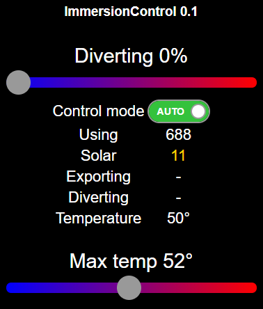
Here’s a screenshot from the ESP8266’s web server, with almost no solar.
diverter

The only reservation I’d have there is accuracy. By taking three values and using a sum and a difference, you might actually end up controlling on the resultant error. Hopefully, it won’t be great, but it’s something to watch out for. I don’t know whether the Owl actually calculates real power, or whether it’s output is an approximation based on a presumed voltage and/or a presumed power factor. Those are also things to watch out for. There’s also another hidden ‘gotcha’ - those readings from two sources aren’t synchronous, so you’re always hoping they haven’t changed much and aren’t changing quickly. Robin says, and knowing his code it’s true, his diverter responds within two mains cycles.

The reservation I’d have about the proposal is the ability of the OWL devices to provide real time readings.

I’ve not looked at OWL in a long time but if they are sending readings at any kind of interval, e.g. once a second, then the algorithm will only be ‘right’ once a second which probably isn’t timely enough.

Both MartinR’s and Robin’s sketches are taking many readings per cycle, so have real time data on which to base the decision as to whether to divert or not.

Also, on the meter point. There was a long thread recently where there was a discussion about meter accuracy, meter reporting on the display and meter charging units.

From my experiment on a new smart meter, it looks as though the meter display accuracy can be and in my case is different from the what the meter sends through to the utility co for charging. I believe that regardless of what the meter can display, there is a standard charging unit in the UK of 3600J - this if you think about it would make sense, it would allow meters to be interchangeable regardless of which utility co someone chose. I’m sure this should be set out somewhere in some legislation but for the life of me I can’t find anything setting this out.

Simon

I thought I’d mentioned both those points, and questioned whether the Owl devices calculate real power. Very few commercial devices do, rather it seems they achieve customer appeal by having displays of cost etc that are likely to be inaccurate but nevertheless look attractive.

Hi Robert, I only made one point and that notwithstanding, I didn’t see anything in your replies about how real-time the OWL readings might be which is a real deal breaker.

Agree with all your other points of course about real power etc.

Simon

EDIT:

The OWL Intuition PV monitor → Solar PV Monitoring | Intuition PV | The OWL

Clearly states in the specs

‘12 second refresh rate (Electricity consumption data)’

So probably a non starter in terms of using that data feed for a diverter

It seems you missed this part:

Thanks everyone for your comments.
I’m only using Owls because I happen to have 2 working. These are 6 second ones, so I get a reading every 1-5 seconds.
Yes, when I make my final version I’ll use CTs, but the Owls are good enough to test my dimmer code.
The RobotDyn dimmer is really easy to use, with its own Arduino library. It does the zero-crossing detection, and you simply tell it what percentage of dimming to do.

I’m not sure how Robin does it, but it seems to me that you have to check that the immersion is actually taking power for the calculations to work.
I’ll use belt-and-braces - a CT on the immersion wire, and a temperature sensor on the tank.

MartinR’s original design - not the one he published - did use a temperature sensor on the tank to turn off dumping, freeing to tank thermostat to safety override duty.

That’s not correct - the algorithm runs permanently, it must do, else it would lock itself out!