@calypso_rae I’m testing my divertor, currently using sketch “Mk2i_PV_Router_rev4b.ino” (as I had compile errors on v5 and wanted to test with a simpler version).
In anti-flicker mode I seem to have a very slow switching cycle, around 20s. I’m using a 750W electric heater as “dummy solar” and a 3kW kettle as dump load.
It seems to be wired up OK, eg 1500W heater power gives a 50% duty cycle and 750W heater gives 25%.
Could you please let me know if this long cycle is normal? Will it work in terms of keeping under the 3600J that my leccy meter would register?
hardware-wise I have Arduino Uno, emonTx shield and a SSR.
thanks!
Hi Simon,
With the 750W generation and 3kW load that you’re using, the load should indeed be on for approx 25% of the time. With a properly calibrated system, I would expect the cycle rate to be around once every second or two, not every 20 seconds. At such a slow cycling rate, the meter’s penalty-free zone would almost certainly be exceeded, and charges would be correctly applied.
The Downloads page of my website at http://mk2pvrouter.co.uk/13601.html has various sketches that may be of interest to you. Mk2_bothDisplays_4.ino is my latest standard code, this follows on from the Mk2i line which only appeared on the OEM forum. The calibration program, cal_bothDisplays_1.ino may be helpful for calibrating your primary measurement channel. If the powerCal value that you’re using is way out (too insensitive), the cycle period when in AF mode will increase accordingly.
The latest version of my Mk2_RFdatalog code (version 5a) has the ADC free-running so the Timer1 library is not used. The structure of this code has been improved so that all of the critical timing takes place in the Interrupt Routine. The main code in loop() then only has to deal with the slower stuff, such as RF, serial and temperature measurements. If you’re not using the RF capability, it can be removed from the code by commenting out the #define RF_PRESENT statement near the start of the code.
If using code from my Downloads page, the IO port allocations will need to be changed to match your hardware. “Mk2” code on the forum is no longer actively supported.
It’s always good to hear where Mk2 PV Router code is being used
Thanks.
To suit my emonTX shield, I’ve changed sketch so the ANA pins are 0(volts) and 1(CT1). I notice you have another CT on the divert, is this strictly necessary for a basic system?
You said in the old forum (14/2/2015):
“The emonTx V3 has four CT inputs, but only CT4 has a sufficiently high sensitivity for control purposes.”
Do you know if this applies to the shield, and if so do I need to be using CT4?
I haven’t yet wired in the Output Mode switch.
Trying this setup, I get a “normal mode”, flickering, trigger.
I then tried the cal sketch you mentioned, which reported values of 40 to 80 when I switched my “solar load simulator” between off, 750W and 1500W. Suggests to me that I’m not getting a decent range of response on my CT, and/or some tuning ofpowerCal.
Sorry, I’ve never used the emonTx shield. I would expect the burden resistors to be of similar values.
My Mk2 sketches have generally been written for a burden of 150R. If your burden is much lower, the signal size will be greatly reduced, hence the very small values that you’re seeing. The ratios look to be OK, so you should be able to obtain the right values just by increasing powerCal by (750 / 40). For optimum sensitivity, and best performance as a balanced diverter, I would recommend using a greater value of burden.
At times of high consumption, high valued burdens could overheat if only rated at 1/4W. I now use 1/2W components for this purpose.
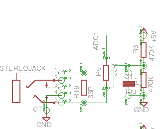
I guess R5 on this EmonTX shield schematic is the burden, 33 ohm surface mount. Just realised that the burden resistor can be changed and the EmonTX shield has holes for as-yet not fitted R5.
I’m using the OEM shop’s 100A CT, so 50mA output max. With only 33ohms burden and at my 1500W load, I would only see ~25mV on the ADC pin. (Guess that’s one reason to use a lower range CT for the diverter as well).
If you fit a higher value burden at R5, you will also need to remove the parallel one at R16. I’m sure you’ll appreciate this, but best to mention it in case anyone in future doesn’t.
The PCB from my Shop supports two current sensors. Only one of these (CT1) is used for the purposes of diverting surplus energy. The second channel (CT2) can be used to monitor the diverted energy. The daily total can then be displayed via a 4-digit display on the front panel of the enclosure (or anywhere else via a standard ribbon cable).
All sketches on my Downloads page make use of this second channel. If no hardware is present, the resulting data for that channel will be meaningless. But the processor might as well be doing something, even if it’s not particularly useful!
Yes! the shield runs at 5v (so +/- 2.5v with the offset midrail) and the emonTx at 3.3v (+/-1.65v) which is why the emonTx channels 1 to 3 have a 22R burden and the shield has 33R burdems despite being configured for exactly the same CT’s and 100amp range.
My rule of thumb (allows for component tolerances) is aim for the burden developing 1.6 V rms at max current for an Arduino running at 5 V, or 1.1 V for an emonTx or Arduino running at 3.3 V.
(Likewise for the voltage input and the output of the a.c. adapter / voltage divider combination.)