Hi
I am using emonTx V3. I have not finalized calibration but I found that my readings are about ten times smaller than what is expected.
I am using a 2Kw boiler to test with. I am reading with both channel 2 and channel 4 and I get the same results.
I did notice that the burden resistor mentioned in the help is 22R but the schematic I followed has two 22R resistors in parallel making the burden resistor 11R. Same goes for channel four.
This is a sample of my message on the serial monitor
That would seem to suggest that there’s nothing wrong with either your c.t. or with the emonTx.
That’s not true. The burden is 22 Ω for CT1-CT3 inputs, and 120 Ω for CT4 input. The “second” resistor is a pair of holes giving provision for a second parallel wire-ended resistor - or indeed a replacement wire-ended resistor if the SMT one is removed. As the units leave the factory, there is no second resistor fitted, which you can see from the photos or if you look.
And if you think about it, an 11 Ω burden would halve the reading compared to the expected value. So something else is the cause of your problem.
Hi Robert,
Thanks for the reply.
I have not ordered the hardware (emonTx) yet and as I needed to do some measurements urgently, I just built up the front end on strip board. The schematic shows both resistors so I followed suit.
Is there anything that I should take care off in the firmware if I only use the analog front end and an UNO?
You should not give false information like that. How do you expect us to help you if you do not give us the true facts? ? ?
Is there anything that I should take care off in the firmware if I only use the analog front end and an UNO?
The big problem you’re likely to see is noise and grounding issues. Historically, whenever we had a user complaining about a reading when no current was flowing, it was a prototype board layout analogue front end attached to an Arduino. Otherwise, check that the analogue reference voltage is set correctly - it defaults to 3.3 V for the emonTx, you probably need to override that to 5.0 V.
Looks like taking the second resistor out and redoing the cal solved the problem. Thanks for your help. I do appreciate it and I am very grateful for your work that you have made available to us.
While it is true that you just left out one word, it completely changed what you said you had vs. what you actually had.
It has been said plenty of times on these forums, we’re not mind readers, so if you say one thing but really mean another, there is no way for us to know that.
A lot of time can be (and has been!) wasted chasing down possible solutions that have absolutely no bearing on the problem at hand because they relate to totally different sets of circumstances.
Exactly. Whilst we know that the emonTx V3 hardware is correct - except for the very occasional fault that develops early on, the same cannot be said of a breadboard construction. So the omitted word totally ruled IN a range of possible faults that were otherwise (on the balance of probability) ruled out.
Is there still a problem? The waveform you provided appears to me to have been posted before you posted this:
Are you now saying it still isn’t working as you expect it to?
Do you have an updated waveform since you removed the second resistor and redid the calibration?
What other things can you tell us about what is/isn’t working? We’re really not mind readers, and if we weren’t trying to help, we wouldn’t be posting…
Do the maths.
You know (we don’t, because you have never mentioned it) which c.t. you are using. You must know the ratio - for our “standard” one, it is 100 A : 50 mA. Calculate the voltage across the burden, convert that into the “counts” out of the ADC, then work through the sketch applying the necessary scale factors - the calibration constant is one of them - to see if you arrive at the correct current & power. If not, you now know exactly how the sketch works, so you can see which of the values you got on the way is wrong.
Also, try looking in the ‘Learn’ section if you haven’t done so already. All the basic information you need is in there.
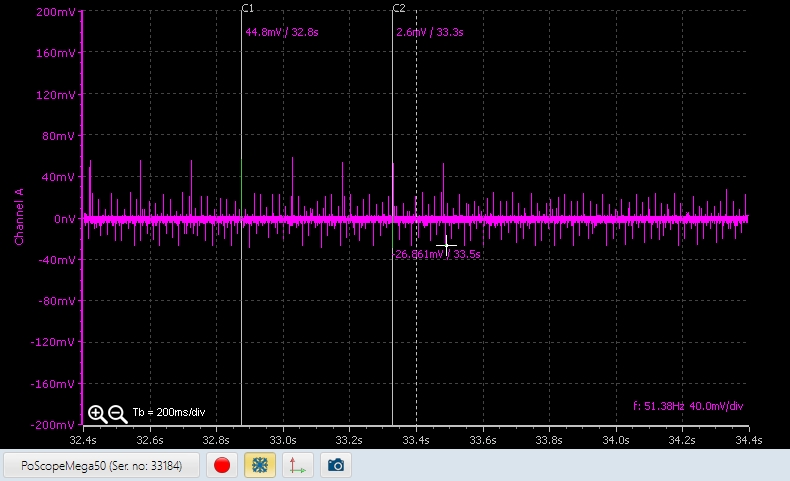
There was mention of noise being generated by strip board circuits and I don’t get a perfect zero when the CT’s are not clamped on an AC wire.
I did take the picture after I removed the extra resistor so that is the signal that I have at the moment. I could get the calibration set so that I read the current to the 2kW load correctly on all four CT’s but as I mentioned the resting wattage is not zero. I am happy to work with that if you say the signal is what is expected.
@Robert.Wall, Just saw your recent reply. I am using the prescribed SCT013 100A:50mA CT’s. Your remark about looking in the code is handy, thanks I will do that.
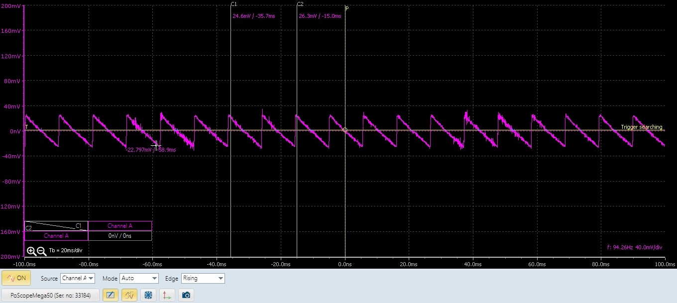
You’re seeing about 50 W of pick-up or noise. Do the maths and convert that to volts at the input of the ADC. What do you get? Given the value that you calculate, do you expect to see a voltage equivalent to that current on a 'scope trace that is 10 V top to bottom?
What you need to do is set your 'scope to a.c. coupled and increase the Y-gain until you see something.
Don’t be too surprised if you see nothing.
Then transfer your 'scope to the power supply. Is there noise or ripple on that? If there is, then even if the voltage across c.t. burden is zero, and the ADC input is rock steady, there will still be a variation in the ADC output because its reference is changing. You can do the maths on that too: say there’s 40 mV peak-peak ripple on the supply, and the ADC input is nominally at half the supply voltage but rock steady (because it’s effectively decoupled by the bias network), it will look - to the ADC - as if there’s a 20 mV p-p ripple on its input. What rms current / average power will that appear as out of the software?
Robert, so it seems that there is reasonable amount of noise on both the ADC inputs and the power supply. I am ok with that for the time being as long as I can measure the peaks and the usage for a couple of days. If it is not 100% accurate it will be fine as it must just help me decide how to spec the system replacing it with Solar.
I will order the emonTx hardware in the new year as I want to have the facility to measure accurately in the future. I am setting up a VPS with the monitor software at the moment.