No, you don’t want the divider voltage to be exactly 9 V, you want it to be exactly (as near as you can) the same as the transformer secondary voltage, and you adjust it until you measure zero volts between the divider and the transformer. Then the divider ratio is the transformer ratio.
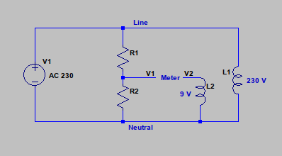
“L1” is the transformer primary winding. “L2” is the transformer secondary winding.
Adjust R1 or R2 (or both) to measure zero on the meter. Note: Measuring Line – V2 should be 221 V, not 239 V. Reverse the secondary winding connections if necessary.
I see, but isn’t the OC voltage of the transformer a problem? It should be higher than in the working circuit, connected to the EmonTX. The input impedance of the meter is normally very high. Should I try to mimic the EmonTX somehow? I can’t connect it to the measurement rig with mains, though.
I thought you were trying to establish the actual voltage ratio of the transformer, so that by setting or knowing the ADC reference voltage and the emonTx’s divider ratio, you could calculate exactly the calibration coefficient?
As I wrote above, the exact voltage calibration coefficient is the mains voltage that produces 1 V at the ADC input. So in terms of the components in the emonTx, that is (R13 + R14)/R14 × [transformer ratio ≈ 230/11.5]. This is where the calibration coefficient 260 comes from.
R13 = 120 kΩ and R14 = 10 kΩ, both 1% tolerance, but “11.5” (Volts) is 5% tolerance. If you can measure the transformer ratio to better than 0.5%, then you improve on your DMM’s accuracy.
You measure the transformer ratio without the emonTx.
You might be able to measure the resistor divider inside the emonTx. The ratio (R13 + R14)/R14 is known only as good as the tolerance allows. If you connect a 12 V d.c. supply across R13 + R14 and measure that voltage and the voltage across R14, that will give you a better value if you can measure the voltages to better than 1%. That should not damage the ADC input if you do it with the emonTx powered and no a.c. voltage input. But if you put 12 V on the ADC input, you will almost certainly destroy it. It’s a risky procedure because if you don’t get the correct points to apply the 12 V, you could very easily kill your emonTx.
My concern was running and measuring the transformer without load, but it seems it’s not a problem in itself. Thanks for the explanation, it gave me some new ideas.
A tangentially related question: what is the expected maximum RMS voltage input for the EmonTX on the mains side (primary of the transformer)? I’ve seen quite high values (above 260V) a few years back when people installed new solar power systems in the vicinity. I installed EmonTX later and I can’t see anything like that any more, though.
The a.c. adapter/transformer normally runs under no-load (almost, anyway). It’s rated at 0.67 A, whereas the normal current even when powering the emonTx is significantly less than that at about 25 mA rms
That is determined by the transformer rating. I believe it will be the normal supply voltage tolerance, i.e. +10%, which is 253 V.
I see, thanks. I’d like to have a (most likely) last question. I could look at the code, but I think it’s worth clarifying outside of it. How is the Vcal used? You wrote that the Vcal reading on the ADC means 1V. But the ADC in the EmonTX only gets 1V input at a certain input AC voltage in the negative swing. Is Vcal only used as the reciprocal of the effective ADC resolution?
Those numbers look right to me. And the negative-going peak is 1.65 V - 1.38 V = 0.27 V.
ADC resolution isn’t a problem with voltage, because the mains voltage range is limited to ±10%.
(In normal circumstances, less than 80% of the ADC range is used).
It’s much more important to use the maximum possible ADC input range with the current input, because real-life current can go from 1 LED lamp (15 mA) to the full house load - easily 30 - 40 A if no alternative fuel is available.
There’s a misunderstanding there. I meant 1 V alternating voltage superimposed on the d.c. bias. Whether you measure rms, peak or peak-peak doesn’t matter as long as you use the same for both voltages.
The 1.65 V d.c. bias does not enter the calibration equations.
Since my numbers are correct, I don’t think there’s any, but if you take the 1V statement literally, one can wonder. And yes, used ADC resolution should be around 80% since 3.03V is the high peak, the negative should also miss the lower portion of the input range similarly.
FWIW, I hooked this meter to my system (no load metering yet). It specifies 1% MID certified general accuracy. No specs on voltage accuracy, but other similar meters made in China spec a 0.5% on voltage and current. It’s probably similar or the same. The point is, it shows a consistent average difference to my EmonTX of -0.7V (about 0.3%). I don’t know what to make of it, but I can probably say that “it’s not too bad”.
EDIT: comparing a 2-week run of my utility meter (certified to 1% accuracy) and the EmonTX import/export measurements shows that EmonTX is about 0.75% higher than my utility meter. Again, “not bad”. But it’s worth noting that I used the flow to measure import/export onn a single CT to make it simpler, instead of the difference of power flowing through 2 CTs (as in the original recommended standard setup). It was just for this simple calibration/comparison run, otherwise I’m using the standard configuration. I might change that, though.