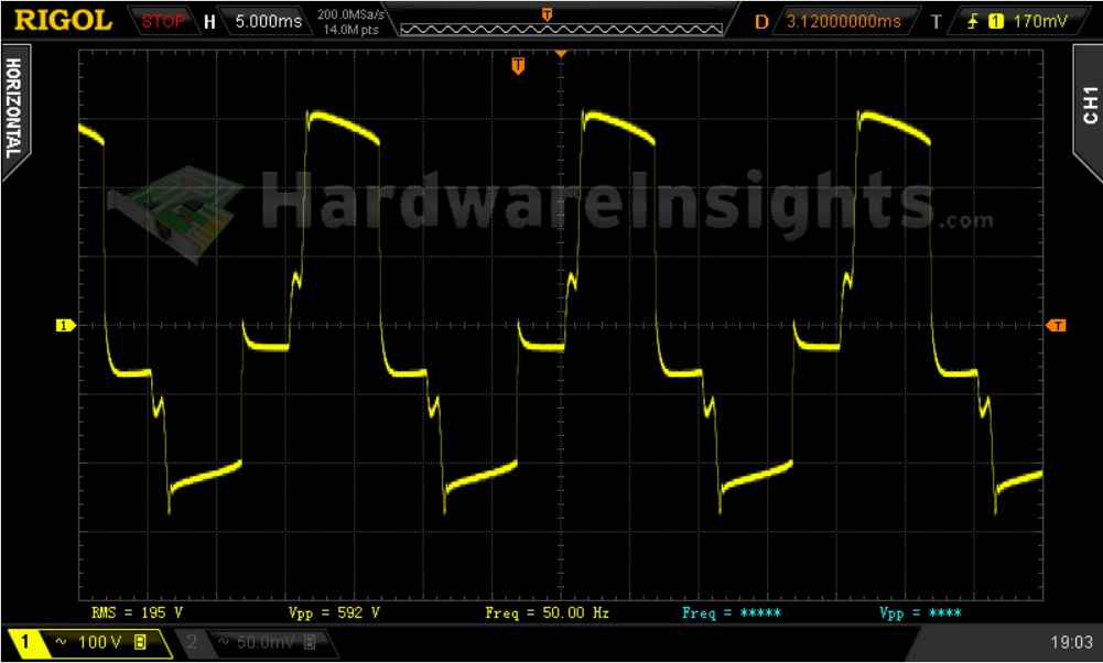
My 230 VAC looks like image attached. It’s not so much “unstable” in the common sense, since it’s always within tolerance and there are no power problems at all - but it does fluctuate a lot around 230V, making calibration pretty hard.
I’ll need to reflash the EmonTX to be able to add a NodeMCU clone running EmonESP. I stored a voltage calibration value in the currently running FW that is now lost, and I’m not completely sure it was right anyway. So I want to recalibrate it. What are the recommendations? I do have a true RMS DMM with adequate accuracy, but it’s next to impossible syncing the serial readings and the readings of the DMM. Should I try recording the DMM measurements for a few minutes somehow, calculate an average, do the same with the EmonTX serial output and calculate the ratio? Something else I can think of is generating stable 230VAC somehow. I have 2 UPS devices with “modified sine wave” output - could they be useful for this purpose? Any other ideas?
I’d suggest trying your UPS first, and see if it is sensible. If it is, use that. Both your meter and emonLib are true rms (over a limited range) so the distorted waveform should have minimal effect.
Second, I’d try to get the emonTx to sample at the same rate as the refresh rate of your meter. I think I’ve got a lot closer doing that.
For that, you could try emonLibCM with the test sketch. It has identical calibration (for amplitude, but not for phase) as emonLib, but samples continuously and reports down to 0.1 s intervals.
Third, do you get a more stable voltage late at night, when fewer people are switching things on and off? (Fridays and Saturdays excepted!)
Night readings are the same, sadly, sampling at night wouldn’t help. Isn’t the waveform affected by the 9V transformer to cause a non-negligible error when applying that altered UPS waveform? If this method doesn’t seem to work out, I’ll try your other suggestion with emonLibCM. The refresh rate of my meter is 1s.
That is possible - it is why I wrote “and see if it is sensible”. I’d suggest getting close with your mains, then try the UPS. If it is close, then use that. If it is significantly different, then it was an idea that did not work.
The time of calibration is nearing, the weather is getting nice. I have an idea. Using the continuous sampling sketch, I measure the AC voltage of the transformer plugged in one of my modified sine wave UPSes, setting the voltageCal constant to show the real voltage of the secondary, and then measure the same with my true RMS DMM. This is all so I can actually measure the same waveform and voltage on a stable source. According to my small research, the waveform can be distorted quite a bit, possibly affecting the actual RMS voltage beyond standard measurement errors. So instead probing my AC line with the DMM directly and the same with the EmonTX “indirectly”, I probe the same output.
Now, my question is, is that idea viable at all? I’m only interested in fixing my voltage sampling first, then I’ll probably calibrate power metering. How should I change voltageCal to see the actual transformer secondary winding voltage? The default in the CM library is 268.97 and I’m not sure how it was calculated.
When you write about a transformer and measuring the secondary voltage, is that the isolating transformer that you are using to measure the a.c. voltage? If so do you know the ratio accurately? Why I mention this is because our a.c. adapters have a ±3% tolerance (UK model) or ±5% tolerance (EU model). And that is a major contribution to the uncertainty of the measurements.
What is the output voltage of your UPS? As long as it is not ridiculously low (say greater than 48 V, I think I would not change anything in the emonTx and simple calibrate at whatever voltage it is. My feeling is you might introduce a bigger error because of the uncertainty in measuring the transformer ratio.
Try to set the sample reporting rate of emonLibCM to be the same as your DMM. It is much easier to compare the values if you can do that.
The voltage calibration constant is the voltage that gives 1.0 V at the ADC input. (Likewise, the current calibration constant is the current that gives 1.0 V at the ADC input.)
Alright, it’s a challenge then. What I wanted to avoid are the errors caused by the distortion of the waveform introduced by the transformer on the modified sine wave. The transformer is the EU one purchased from the OEM shop. The UPS nominal output voltage is 230V. I might think of devising a working method where my reference is the DMM with a known accuracy but it seems to be a dead end now.
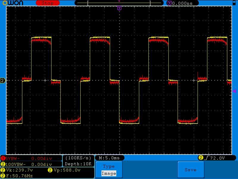
If your waveform is like that, then is it possible to add a low pass filter to the output, which would attenuate the higher order harmonics? As long as the emonTx and your DMM have a similar response to harmonics, then it’s not necessary to ensure that the waveform is free from harmonics. However, that is likely to be as difficult as establishing how both react in the presence of a substantial harmonic content.
I don’t know if my waveform looks like that (I don’t have a scope to check), but the modified sine wave is distorted like that, when passing the transformer (a similar one), apparently. I don’t really want to make the sampling more complicated with filters, I just want to eliminate this kind of error for calibration, if possible. But I think I’ll do the more tedious manual procedure instead.
I’ve found something actually useful. I have a smaller one from the Eaton ECO series, the ECO 800, which most likely has a similar or identical output to the ECO 1200.
Do you have a signal generator that can deliver a stable 50 Hz sine wave, a reasonably high powered audio amplifier and a mains transformer that you can use ‘backwards’, so as to generate your own stable “mains” voltage?
Oh, thanks, I’ve been playing with that idea too. Signal generator → 9V transformer used in “reverse” → EmonTX/DMM. My PC is hooked to a power amp via an external DAC, so it should be doable using the sound card.
But I’m not sure it’s worth the effort. And I checked my DMM’s VAC accuracy (it’s an Extech 430, a mediocre, but fairly good one) in their datasheet, and it’s listed as 1.5% so I might want to first calibrate the DMM (with eg. a cheap, but accurate voltage reference)… It’s getting complicated.
Whatever calibration to do, it is only as good as the reference meter that you use. You cannot escape from that.
And remember, a meter’s accuracy depends on the range you’re using and the value of the reading. Most DMMs have an accuracy statement like (±1.5% + 3 digits), so this meter, on the 10 V range, could read 9.000 V as 8.862 V or 9.138 V, or anywhere in between, which is ± 1.533%
It’s worse at the low end of the range: 2.5 V is too high for the 2 V range (on a 3½ digit meter) so on the 10 V range it could read between 2.46 V and 2.54 V, which is ± 1.6%.
Your best course is likely to be to set the voltage, current and phasecal as best you can with your multimeter, then compare the energy recorded by the emonTx against the meter’s value.
If your electricity meter has a pulse output, you could speed up the process by modifying the emonTx to generate pulses at the same rate as your meter, then compare pulse rates.
Yes, thanks, I’m aware of the accuracy woes. I remembered the DMM’s AC accuracy was better, but apparently it’s not. That’s why I’m pondering using a “cheap, but accurate voltage reference” to calibrate something. I don’t know yet, what, but my best bet is the DMM so I can have a known secondary reference.
It’s not likely, but it is possible: If you calibrate your meter on the 2 V d.c. voltage range (likely to be the most accurate) and that’s also ± 1.5%, it could be on one end of the tolerance range and the 300 V a.c. range on the other, so you are 3% wrong.
Right - though the DMM is claimed to be 0.5% for the low DC ranges, so it’s a lot better there, in theory. I could calibrate the ADC of the 328p with a voltage reference, but then what about the transformer… I’m aware I might overrate the importance of additional calibration but if I do it I at least want to do it properly.
Exactly - the two transformers, c.t. & v.t, are the weak links that will throw the calibration off.
If you have a range of high-precision resistors of suitable values and power rating, you could try setting up a ‘modified’ bridge circuit.
You have a voltage divider across the mains, made up from resistors. That’s two arms of the bridge, and the voltage across the ‘bottom’ resistor (possibly a combination of resistors) is nominally 9 V, with the full 230 V appearing across the complete chain.
The other side of the bridge is the transformer. The primary sees the full mains voltage, you connect one side of the transformer secondary to mains neutral so that the other end of the secondary subtracts from the mains voltage.
(If you can’t understand the connections, I’ll draw a diagram for you.)
Now adjust the resistor ratio to give the minimum voltage between the mid-point of the voltage divider and the other end of the secondary winding. You won’t get zero volts due to the phase error in the transformer. The resistor ratio is then the same as the transformer ratio. If you use 1% resistors, you should get to within somewhere close to 1% worst case. (I’d need to think very carefully what the actual error could be, because part of the error is shared by the two voltages!)
Yes, I think I get it. I can get precision resistors down to 0.1%, that shouldn’t be a problem. I think getting the divider ratio to give exactly 9V is not very important (but something close enough), since we’re interested in the transformer ratio. I’ll think about this…

