A lot of the posts I have found on the subject of using multiple CTs to monitor different circuits are quite old. For 2018, what’s the best hardware option to use to read multiple CTs that also has built in wifi so I can post the results via MQTT?
My goal is to be able to track when major appliances in my house are running and for how long (well pump, hot water heater, hot tub, dryer, etc). I also want to be able to check for rapid cycling on/off. Knowing the kwh consumption is a secondary but nice bonus to have.
FWIW, I already own 4 YHDC 030-013-030 (30amp, built in burden resistor 0-1v) so i was planning on using those.
I’m quite familiar with ESP8266, but having only one analog input pin makes it a bad choice for this. I thought I could add an I2C ADC (like the ADS1115), but the sampling rate - especially when switching channels - seems to be very problematic.
What about the Adafruit WICED Feather? It has a 120mhz STM32, wifi and 8 12bit analog inputs - any concerns with using this board?
I’m not familiar with the Adafruit product but I am a big fan of the STM32 line of processors. While using them for non energy monitoring related projects, I’ve often thought what a kick-arse processor they’d make for energy monitoring. The STM32F205 used in that Adafruit product actually has 3 high speed ADCs, each capable of synchronised 0.5usec 12-bit conversions (subject to source impedance).
That means you could do synchronised simultaneous sampling of 1xV and 2xI channels with none of the typical firmware delays associated with starting the ADC conversion. In addition, you can leave it free-running and DMA-ing the results straight into your C array, so you can set things up such that you get a single interrupt to tell you that your 3 big arrays have been loaded with the 3 x thousands of 12-bit samples you requested. It’ll immediately and autonomously go onto to work on the next batch of 3 leaving you with a 120MHz ARM processor to work on the last batch. There is zero CPU involvement in doing the conversions and loading them into your C datastructures.
That’s the theory anyway, and I’ve got one doing just that in an unrelated project. In reality you’ll be limited by:
which pins Adafruit have chosen to break out for use
how flexible/powerful Adafruit’s runtime environment is
Almost all of these environments have a tendency to dumb things right down to the simple block-until-complete analogRead() model carried forward from the Arduino world. If you’re prepared to break away from that you can get some stunning performance out of these modern micro-controllers.
I have never used an STM32 but some recent research has resulted in me wanting to try an STM32 based monitor, I do not recall the models I was looking at but the processor speeds and number of SDC inputs were the main attraction.
Working entirely from memory here, I recall a model was spec’d as 21 ADC channels, 12bit and 5msps. at the time I couldn’t definitively find the specific number of actual ADCs and whether the “5msps” was total or per ADC, (if indeed there were more than one ADC). since the same device had 2 DAC’s I sort of expected it to have more than one ADC.
I would really like to explore using a STM32 as multi-channel energy monitor with both plenty of channels and plenty of oomph for continuous monitoring at a high enough speed and resolution to be able to explore appliance recognition and/or fault recognition. And the STM32 looks a good candidate. I would aim for a dedicated serial data stream (several serial ports being another STM32 advantage) so that I could either add a usb serial chip (eg FT232RL) or a dedicated WiFi chip like the esp8266, which if it wasn’t doing the monitoring, would be able to provide a really good AP mode or api/config/calibration web page.
Nice to hear we have a resident STM32 expert That could be handy!
What environment do you use? STM have their own don’t they? I believe the Aduino IDE will also cater for some, but I’m guessing that might offer fairly limited resources.
I also seem to recall some had in-built op-amps too.
Come on in, the water’s fine! They have a huge range. At the higher level there is the “family”: F0, F1, etc etc. and then within each family lots of options with regards RAM and FLASH sizes, number/types of peripherals, number of pins etc. etc. You can start here and drill your way down:
I played with quite a few, but in the end my requirement to be able to change CPU choice with a day’s notice, and use their latest CPU offerings, meant sticking with their HAL. All the other HALs I tried lacked support for the latest CPUs (“coming soon”) which would mean taking time out of from what I was trying to build in order to add that support.
I ended up with a sorta’ hybrid solution. I use their STM32CubeMX GUI tool to configure the project, map pins to special functions, create the source files, and add all the hardware and HAL initialisation code. It creates source files with lots of “add user code here” sections. At first I found all this a bit clunky but over time I’ve grown to love it. The HAL is all open-source so you can poke around and see how things work. I didn’t go the whole IDE path though… I just use the standard ARM gcc tools, make and emacs, but I’m a bit old-fashioned like that. I believe it integrates with several IDEs if you’re that way inclined.
[EDIT] And their development boards are dirt cheap…
Ok! So I decided to dive in and ordered a Nucleo-64 proto board with an STM32F303RET6.
Which I believe to be an ARM® Cortex®-M4 32-bit CPU with 72 MHz FPU and have 22x 12-bit ADC channels across 4 ADC’s capable of 5msps each, RTC, on-board op-amps. 520kb flash, 80kb sram, but I got so lost in the options and choices I could be wrong That’s a lot of MCU for a tenner.
I’m guessing I might not get to use all the ADC’s as they have alternative tasks, eg uart0, but there are several uarts so I shouldn’t lose adc’s to “the” serial connection.
Ideally I’d like to retain at least 18 ADC’s for 3x Vac and 3x6x CT’s, I believe I would “lose” a minimum of 1 per op-amp used, but I wonder if that “lost” adc reading might actually be used directly for offset removal if the op-amp is used for the “mid rail”.
(Unfortunately?) they don’t seem to have eeproms, but I understand they have “eeprom emulation” to use a portion of the flash, which shouldn’t be a problem as calibration data doesn’t need writing very often, and I believe the flash to be faster than eeprom for reading so a “calibration map” for non-linear Vac phase correction should be achievable without impacting the calculation speeds or bogging the sram down with loaded maps.
Sorry Paul (@fahrvergnuugen) - We/I’ve hijacked your thread a bit.
I guess you have looked at the IoTaWatt already?
The Adafruit WICED Feather looks interesting, but I think at $35 (and currently out of stock) I would perhaps spend less on a STM32 with more ADC’s and to that add a cheap esp8266 running emonESP and save a few quid whilst getting more channels as you would still need to add the monitoring front end for either option.
Cheers Simon, I shall have read later. I bet you can guess where I’m heading with this…
I think a Pi Zero W + STM32 with up to 21 ADC channels would make a superb total solution. full emoncms and IoT server with oodles of very accurate monitoring channels, for not a lot of money.
Exactly. I bought some ‘red pills’ as I think they are called last year but haven’t had the chance to really get to grips with them yet. Another option of course is the esp 32 but I could never find a fix on what the ADC on those could do. Maybe time to check that out again.
These things are ridiculously cheap and amazingly powerful - time definitely to move on… (in my case still moving on from starting on an Elliot 903… and some other pretty basic old systems - the processors for the Philips telephone exchanges took the biscuit - if I remember correctly there were 9 instructions and mountains of paper tape).
Roger Clark has done a lot of good work, so well worth digging into what they’ve done.
Indeed, and to be honest I’m more at home with the Arduino IDE so I could be easily tempted to be lazy and use Arduino rather than get to grips with another environment, However, stm32duino is predominantly aimed at F0 and F1 devices, and to get the number of channels I seek, I needed to look at the F3’s (or so I understood).
There’s sorta’ three dimensions to this. It seems complex when you first encounter it but once you start playing with their GUI configurator tool it starts to make sense. The three dimensions are:
number of ADCs (you’ve got 4)
number of channels feeding each ADC (i.e. width of MUX in front of each ADC)
processor pins (you’ve got 64, but not all can be used for analog)
The value for item 2 varies from processor to process, and from ADC controller to ADC controller within the processor, but typically in the 9-15 range. Some of those channels are hardwired to internal signals (Vref, Temperature sensors, OpAmp outputs etc) but most are connected to external pins via a matrix switch.
Assuming you just want to use a single internal op-amp in voltage follower mode (which seems the most popular way of building a low impedance mid-rail) then I think you’d lose 2 pins to that (Vin and Vout). The op-amp Vout is internally connected to one of the ADC’s input channels, so you could sample it for free (i.e. without losing a further pin).
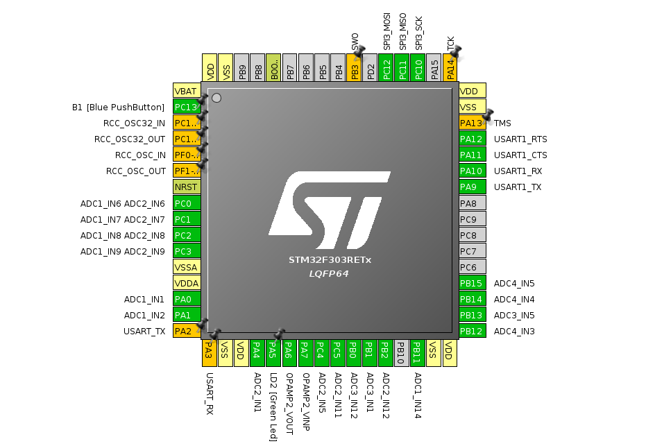
I fired up their configurator tool (STM32CubeMX) set to your board/processor and without trying too hard was able to get 17 analog inputs (a little short of your desired 21):
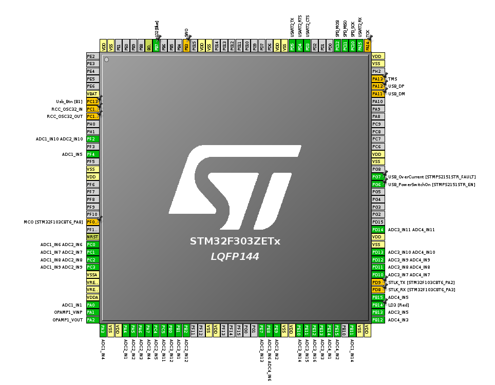
Analog pins are the scarce resource. You can easily get one more (PA5) by removing the Green LED the development board has connected to that pin. There’s a solder bridge for just that purpose and I removed mine because I too was short of analog pins. Failing that, I think moving to a 144 pin device would have you drowning in analog pins. For kicks, I tried that in their tool and was able to get you 35 channels:
The really good news is that so long as you’re sitting on top of their HAL, it’s quite easy from a f/w point of view to change from one device to another. So you could do all your development on the 64-pin device and move up to the next one if/when you decide you need more channels.
Yes, fortunately the uarts don’t generally conflict with the analog pins, so you’ve lots of pins to support that. In the two examples above I even threw in h/w flow control (so 4 pins in total for you uart). That’s probably a huge overkill for your output stream but you’ve got digital pins to spare.
Yes, I’ve not played with that. I always put a FRAM chip on the SPI bus for that sort of stuff (which is why I enabled a SPI controller in the pinouts above). I didn’t include a /CS for that, but all those unallocated grey pins are available as GPIOs.
It sure is! It’s a lot gruntier than any of the ones I’ve played with. Single cycle floating point divide! You ought to be able to have lots of fun with appliance recognition with that much horsepower.
I did actually mean 18, that should have been “18 ADC’s for 3x Vac and 3x5x CT’s” I was thinking 6 ADC’s per phase not 6 CT’s per phase. So disabling the LED would work well to give me the 18 ADC’s I need. Thanks for working that out.
I had looked at the 144 packaged chips but I thought that was a tad frivolous. I’m thinking a 64pin package might be significantly cheaper and demand less PCB real estate if this was to go to production. Not to mention the headache of trying to populate the first batch of boards by hand, I think I will struggle with 64pins
It’s far more sophisticated than anything I’ve tried playing with before, so baby steps, first I will aim low and just try to replicate an emonTx type affair using CM and more channels.
I’m sure there’s loads more to discover along the way.
I also noticed the I-NUCLEO-LRWAN1 on my travels, which is also very interesting, although a less powerful device, it has on-board LoRaWAN and it’s ultra low power. Looks a perfect candidate to slap a 3V3 version of the emonTx-shield on for a LoRaWAN emonTx. The current emonTx-shield is only £11 and this device is only £26. Something @glyn.hudson and @TrystanLea might be interested in as they have started dabbling in LoRaWAN.
Sounds like a solid plan. I think that could form a very future-proof basis for further development. Your choice of the M4 is a good one as it includes the DSP instructions. It’ll be interesting to see if the MAC (multiply-and-accumulate) instruction can be of any use when calculating real power. That lets you multiply two numbers together and add the result into an accumulator all in a single cycle. And the SIMD (Single Instruction, Multiple Data) instructions gets used in the CMSIS library to provide very fast FFT implementations. I believe voice recognition and appliance signature recognition is best done in the frequency domain, so that may end up proving very useful for anyone wanting to go down that research route.
Hey Paul (@pb66) no worries at all. I’ve enjoyed the discussion going on here.
I’ve looked into the design of the IoTaWatt and see that its an ESP8266 with dual external ADCs (MCP3208s) which are 12bit and 8 channel.
In my testing it takes the ESP8266 around 150ms to sample it’s A0 pin 1480 times. Assuming the MCP3208 would give similar performance and you had 8 CTs hooked up, doesn’t that mean that each channel has ~1 second gaps between being monitored? (7 * 150 = 1050ms)
Do you just fill in the missing data by keeping track of the sample duration?
Meaning if I measured 100 watts, then wait 1 second, then measure 100 watts again, calculate the watt hours in a way that it assumes the current was a constant level during the 1 second between samples…
Given that disadvantage of having many channels hooked to an ESP (or Uno for that matter) - I assume the STM chips can sample a lot faster than the ESP8266 since they seem to be a lot more powerful. I’ve even read that some have dual ADCs, though I have no idea how to write code in order to take advantage of having two separate hardware channels.
The wiced just came back into stock. I can’t decide if I should just buy it and hope it works out, or order a few MCP3208s instead…
Personally I have no involvement with the IoTaWatt, but yes I believe it is not unlike the discreet sampling emonTx and it calculates the power and energy for the full time line from a partial sample set.
My understanding of how the IotaWatt works (although it may be best to ask Bob Lemaire over at https://community.iotawatt.com/ as Im not 100% sure I have this right) is that it samples one mains cycle from one CT channel then yields to the webserver and service queue before looping back around to make another mains cycle sample from the next CT channel. The loop source code can be found here https://github.com/boblemaire/IoTaWatt/blob/master/Firmware/IotaWatt/Loop.cpp. It manages about 33 cycles per second on @glyn.hudson’s IotaWatt. Which means that on 50Hz and a single configured CT the power measurement covers 33/50 = 66% of the time, with 2 CT’s the 33 cycles/second is divided between 2 CT’s. Each CT’s power measurement is therefore based on 33% of the time. With all 14 CT’s each channel is sampled for 4.7% of the time. That’s still better than the EmonTx discreet sampling which spends 300ms every 10s on each channel or 3%, the samples on the IotaWatt are also spaced out over the full period which will give better results rather than all in one run in the case of the EmonTx. @Robert.Wall is working on continuous sampling code for the EmonTx which covers 100% of the time, which is currently in testing.
Its worth noting that even with discreet sampling covering 2-3% of a 10s period most of the time you get good results see accuracy discussion https://community.openenergymonitor.org/t/meeting-summary-draft/6821. The problem arises when you have fast switching loads such as a triac based solar pv diverter or induction cooker.
That’s great info @TrystanLea. Does @Robert.Wall have the continuous sampling code on a github repo somewhere? I’m interested in learning how it works.
It was developed from and closely follows calypso_rae’s energy diverter, which is documented in ‘Learn’.
I don’t intend to release the updated emonLibCM until we are sure that it’s working correctly and accurately. The early version still on GitHub shows serious measurement errors that crept in during its conversion, and should not be used. Although the basic code is the same, there are many changes that were intended to and appear to have improved the accuracy, even in areas where there was no fault, so although that will give you the general idea, it’s probably not worth wasting too much time on it.
Yes, I asked for that to happen when the errors were discovered and I started working to correct them, but it didn’t. There are plenty of warnings on the (old) forum.
 That could be handy!