Well done and good effort doing all of that off your own back!
Out of curiosity was it the REG_RSSITHRESH register ? Or something else ?
Thanks
Hello @alandpearson, it seemed to be due to ‘automatic frequency correction’ (AfcAutoOn) being off, register 0x1E needed to be 0x2C rather than 0x0C. However after further ongoing testing there’s still something not quite right and it’s really hard to pin down. I thought I was narrowing it down to an issue with the receiver board PCB that I have here and interference with the Pi that it’s sitting on top of but it’s still not clear. It takes at least 12-24 hours of a test to see what packet loss rate it settles at so it’s a bit of a difficult issue to debug quickly.
It’s not a critical issue for the EmonTx4 as standard approach for the data connection to the Pi will be via a USB-C cable. The onboard serial-to-usb converter makes this a much neater setup with the EmonTx4.
It’s more of an issue to make sure that’s resolved for the emonPi v2, which needs to be a reliable receiver for all 433Mhz nodes.
I tried different RSSI thresholds and dont think that’s having a significant related effect but it might be good to look into that a bit more. Here’s the latest version of the RFM69 receiver library that Im using and all the registers that are being set: https://github.com/openenergymonitor/rf69/blob/avrdb3/rf69.h#L194
Thanks for asking!
Production has unfortunately slipped back a bit further again, it’s now looking more like mid October. This was partly due to a need to check one issue that came up a bit late on our LDV testing for the power supply, that’s now resolved and the PCB’s are in production with assembly to follow. Apologies for the delay on this!
We’ve got the next set of prototype PCB’s on order, including a number options that should be useful in the context of our discussions above:
-
A basic single phase voltage sensor unit without the integrated power supply. Intention is to have a lower cost option here that would work alongside a separate USB power supply (pricing to be worked out after timing the assembly time).
-
EmonTx v4 Pi pico adapter board. This would sit between the emonTx4 PCB and the Pi Pico providing a tidy way to integrate the Pi Pico inside the case. A little related prototyping here: emonTx4 & Pi pico.
-
EmonTx v4 Pi zero adapter board. Similar to the pi pico adapter, allowing the pi zero to be mounted inside the EmonTx enclosure.
-
ACAC 9V adapter to R11 converter board: May allow use of the AC adapters used with the emonPi and emonTx so far (with the caveat of this being lower accuracy than the new precision voltage sensor approach).
2 Likes
The latest set of PCB’s arrived today. Here’s the Pi Zero W with adapter to mount on the EmonTx4:
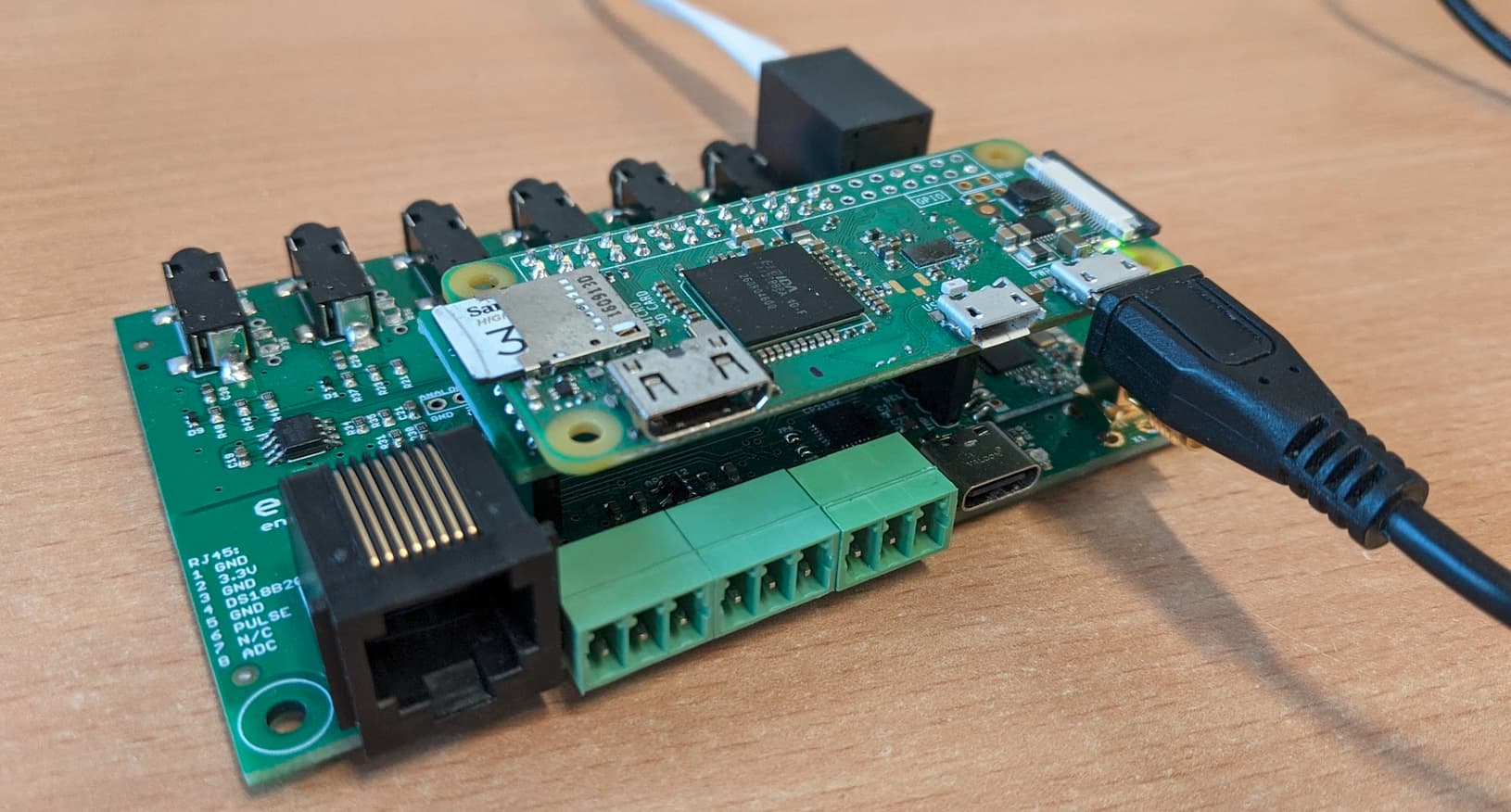
and another adapter for the Pi Pico:
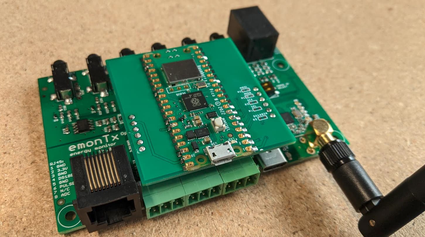
There’s more on the Pi Pico here for those interested emonTx4 & Pi pico - #2 by TrystanLea
I also built up the single phase precision voltage sensor (without the integrated power supply) and the ACAC Voltage adapter to RJ11 converter:
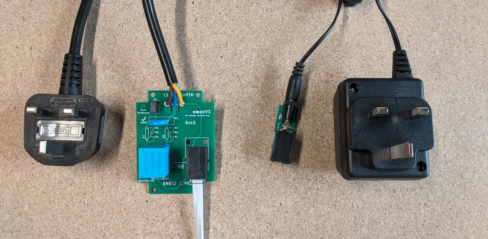
It looks like the single phase precision voltage sensor without the power supply will be about £28 ex VAT (£34 inc VAT). The ACACadapter to RJ11 converter with an AC adapter is probably ~£12 ex VAT (£14.40 inc VAT), or ~£3 for the converter only.
Hopefully these will provide a good set of options at different price points and capabilities. I think it’s going to be good having the capability to support the different platforms: Pi3/4, Pi Zero, Pi Pico and ESP32 with the adapter boards it should provide more flexibility especially in these times of chip shortages. The intention is to provide the ESP32 and Pi Pico options with basic software examples to start for those happy to compile and upload code and then develop these options further over time. I dont think Glyn has had any luck sourcing Pi Zero’s so its likely that we will only be able to stock the adapter board for those who have spare Pi Zero’s already, at least initially until stock becomes available.
Manufacturing of the emonTx4 and emonVs is still ongoing, I will update with more news on that as soon as we know more.
I think this is outstanding - well done all.
No I think this is a policy from Pi Foundation, but having the option for the end user is fab!
From the picture, you seem to be powering the PiZero externally. Does the adapter board not pull power from the TX4 board?
[edit]
Is the RFM chip going to be optional? With so many Wi-Fi options, it seems to me that the RFM feature will rapidly become redundant.
Thanks @borpin! Yes pretty happy with how this is shaping up.
Unfortunately I made an oversight in not routing the 5V rail to the uart connector on the current version of the EmonTx v4, I had thought it would not be needed. The onboard 3.3V supply does not provide enough power for the Pi Zero and so yes it does require the external supply - though that can be supplied from the single emonVs voltage sensor and power supply (which has two outputs). The next version of the EmonTx4 will have the 5V rail routed through to the uart pin allowing the Pi Zero to be powered without the additional cable.
The Pi Zero adapter does have the option to power the EmonTx4 if voltage sensing without the integrated power supply is used.
No not on the first batch at least but I can see your point and it’s probably something that we should think more about on later versions.
1 Like
Rats! Is there any where a jumper wire could be easily connected from? Powering internally is one of the key benefits.
No easy jumpers unfortunately but our first batch is not that large and I’d expect that we will be on the next batch by the time pi zero’s become available anyway.
The pi Pico and esp can be powered internally via 3.3v so those are fine.
2 Likes
It would probably be a bit too much of a bodge to sell boards with this but you could theoretically easily run a DIY bodge wire on the back of the board from the 5V pin on the RJ11 to the UART connector.
The only possible concern would be the extra current flow through the analog ground section throwing off the readings. But that would probably be negligible.
Just a thought.
1 Like
Yes, that’s a good idea, it would also be possible with care to solder a link from the 5v input to the voltage regulator, but it’s perhaps a bit fidly given that its quite a small SMT part.
I’m behind the curve here, but I noticed today there is a Pi Zero 2!
1 Like
Raspberry Pis are amazing but currently they are sold out everywhere owing to massive demand. I have a Zero 2 W and it is a very welcome upgrade over the original one.
The Raspberry Pi Pico W is worth considering instead though. It’s cheaper, there’s greater supply, excellent documentation and an increasing amount of information and examples available on the web.
Just in case you did not see it, Trystan has been working on that too.
We (The OEM Shop) have good stock of Raspberry Pi 4’s ready for the short to medium term, so that is what we will be shipping. But thanks to Trystan’s hard work, there are options available for the user and the future.
I had to check twice but I assume that “The OEM Shop” is https://shop.openenergymonitor.com/. I assume that you mean that you have a stock of Pi 4s ready to go when designs are finalised. Because, at the moment, Pi devices appears to be out-of-stock.
Yes, correct. The emonPi units are out of stock because we can’t get hold of Atmega328 microchips to manufacture any more of the electricity monitoring boards that sit on the Pi.
That is the reason we are moving to a platform based on the newer chip as detailed in this thread.
1 Like
I have a question regarding the CT expansion board.
I noticed from the PCB picture you posted on May 10th that you changed up the sensing circuit a bit. From what I could tell you were using something like this.
Which while using the exact same components does seem like it could be better than what’s used in the tx4 main board as it is functionally the same but removes any possible bias that could be applied by the 0.512v divider.
I’m just curious why you didn’t end up using this in the design you posted on github.
Was there an issue with it? Or was it just unnecessary?
Hello @brandon3055 the main reason for the change to the new design is that providing a low impedance path to ground by grounding one side of the CT really helps with noise at low power levels.
I have since updated the design for the expander board as well to match.
1 Like