Auto hertz - Energy Monitor and Diversion with howto instructions

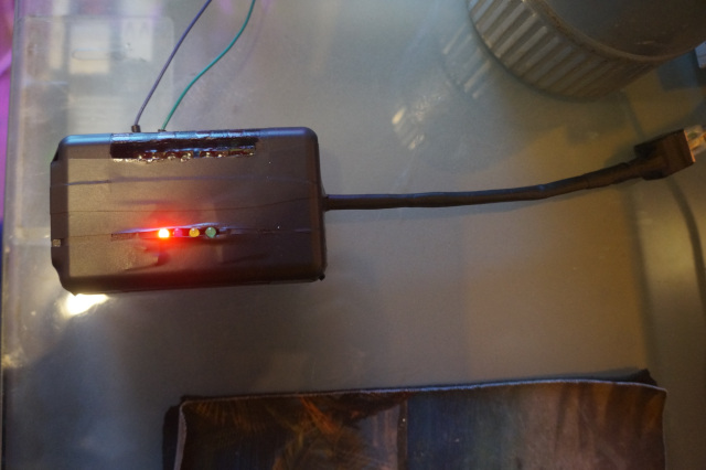
Here is the “finished” version Energy monitor and Diversion.
Supported Features:

  1. it has options to work with or without LCD Screen Display - if using LCD screen you have the use of only 3 CTs
  2. it can support up to 4 SSR and 4 Relays in Cascading fashion for diversion
  3. it has web interface via espeasy firmware to display information from the device
  4. supports multiple Controllers - via espeasy interface- Domoticz, Home Assistant , EmonCMS, Things speak, FHEM etc …
  5. highly configurable

firmware can be found here

Parts required:
emontx arduino shield
wemos uno/wifi or just UNO if you want to run as standalone
Prototype PCB Board For Arduino UNO
2 RJ-45 ports
optional:
i2c LCD for display 20X4
5v 4 channel relay ( powered externally)
SSR +40 DA
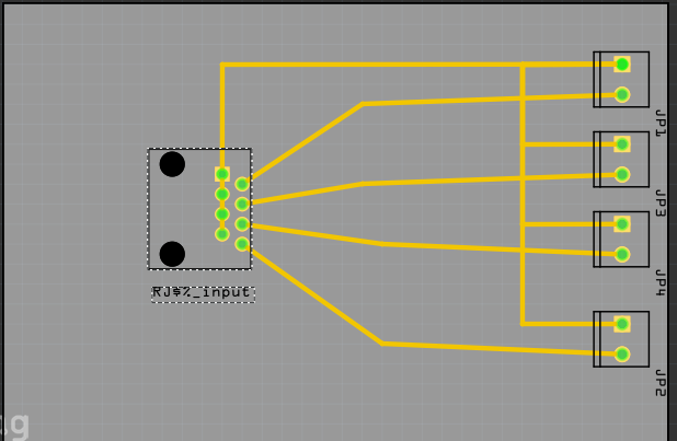
small pcb prototype , 1 RJ-45 port , and 4 2p terminal ( to make ssr RJ-45 terminal block for controlling SSRs

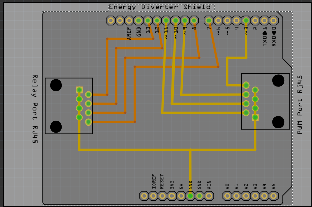
making of the emontx daughter board:
it if pretty simple and straight forward. you can either use rj-45 ports or easier is to use rj-45 extension cables cut the male end off and simply solder the pins - which is basically all the stripped wire to ground and the others solid colour wire to the corresponding pin

energydivertershield

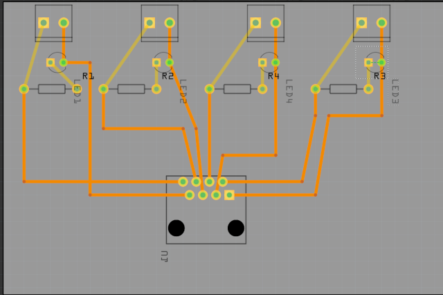
the SSR terminal Block:
part23

uploading the firmware:
UNO ( requires servo hardware PWM (Danial duller ) found in the Arduino library)
if just using as stand alone with LCD an UNO will work fine simply upload the firmware after enabling the LCD and adjust the emontx settings as currently they are set to my region. and set the number of SSR you will be using (ios) currently set at 3.
attach the emontx shield and daughter board and you are done… ( note you will have to disable CT4 on the emontx shield if using stackable emontx simply bend A4 pin over so it does not go in)

Wemos uno/wifi;
if running with Wemos you can operate either with or with out LCD ( note: same as above you need to disable CT4 if using LCD if using stackable emontx simply bend A4 pin over so it does not go in).
configure the firmware as you like ( LCD, # SSR, # CT and emontx settings).

on wemos set all switches to off, except 3&4 are on. flash device as you would normally flash an UNO with Arduino IDE.

next download espeasy
run it easy flasher software
you will be using the esp8266 normal 4 meg flash.

simply set all swtches to off except 7,6&5 press the esp reset button plugin wemos into usb port release and then flash esp.
once done set all switches to off except 1&2. attach emontx shield , daughter board and LCD (if using) – connect up plug in power adapters connect SSR and relays if using as a diversion controller.

setting up espeasy–
once every thing is hooked up if using LCD you should see your energy usage and other info displayed on the LCD screen.
now simply log onto espeasy firmware via the web interface. go to the devices tab > click add on task 1 > generic dummy device> give it a name > enable> select quad out put and set interval to 1 second . then press summit. once the page reload you should see your data out put from CT1,CT2, CT3 and voltage. give each a name, and press summit again and then close…
now press add again on task2. and repeat as above. but this time it will display info for cascading step, static step, hertz and CT4.
now you can up load data to your controller. click controller tab and select controller you wish to upload data too. click and configure to your settings
if you wish to up load to custom controller go to rules

Example : here I am sending data to MQTT Energy monitor LCD screen display. and because my diverter Sensor wire was so long it it picked up some noise so I adjusted the output slightly to read zero

on Diverter#Grid do

  Publish /grid [Diverter#Grid] 
endon


on Diverter#GTI do
 Publish /wind [Diverter#GTI] 
endon

on Diverter#MISC do
TaskValueSet,12,2,([Diverter#MISC]-13)
 Publish /energy/divert [AvgDiverter#MISC] 
endon

for more detail instruction on flashing

okay good luck have fun

1 Like

here a basic terminal block with LED lights for easier visualization of where it is in the cascade…
example; red (SSR1), blue (SSR2), yellow (SSR3) , and green (SSR4 but also seconds as a light that tell you relays are activated if using PWM.h since that only supports 3 SSRs)

terminal block with led

DSC05314

Update functionality:
Added more functionality to my energy monitor…

manual control of SSR 1 output for scheduled purposes

You can use espeasy firmware or home automation software to schedule events such as once a week heat your hot water tank to 70 C - temperature control by either espeasy or a mechanical switch on your tank ( this would be my preferred method for safety reasons )

automation software__

http://your_ip/control?cmd=pwm,12,0           sets ssr1 to auto for diversion and off
http://your_ip/control?cmd=pwm,12,1023      (  10 - 1023 - manually sets ssr1 at a fixed pulse for  for scheduled events

within espeasy firmware in the rules__

 On Clock#Time=Sun,18:25 do 
  pwm,12,1023
 endon

 On Clock#Time=Sun,19:25 do  
  pwm,12,0
 endon

manual and automatic control of the relays via home automation software or espeasy firmware–

there is auto function- this is determined by the diversion it will cascade into each switch as more load is required. if enabled it is saved into the eeprom to maintain setting after reboot. there are 4 relays that can be enabled or disabled. if disabling auto function disable from 4 -1…
and manual control for use via espeasy firmware or home automation software …

pulse setting are as follows

switch1  auto(355) off(325) on(295)
switch2  auto(265) off(235) on(205)
switch3  auto(175) off(145) on(115)
switch4 auto(85) off(55)  on(25)

there are 0 - 900 so there is alot of room for other switching configurations if you would like more options

example :
home automation

http://your_ip/control?cmd=pwm,04,25   turns on switch4 
http://your_ip/control?cmd=pwm,04,55   turns off switch4
http://your_ip/control?cmd=pwm,04,355   turns auto function on for switch1

example espeasy firmware

On Clock#Time=All,1:30 do   // every day at 1:30 hours  turns on  switch 2...
  pwm,4,205  
 endon

On Clock#Time=All,2:30 do   // every day at 1:30 hours  turns off  switch 2...
  pwm,4,235  
 endon

when setting up espeay firmware under hardware set gpio-12 and gpio-04 to low output
in devices as above add a task 3 named outputs with single input and interval of 1 second
and insert this into the rules

on outputs#switch>0 do
pwm,4,0
endon

this rule turns off the pwm once the switching info is received

on the wemos R3 (uno/wifi)
you will need to run a lead from gpio-12 on the esp header to pin 6 on uno board this is the pwm override control
and you will need to run another lead from gpio-04 to pin5 on the uno board.

the newest firmware for this is found here

https://github.com/krywenko/auto-sensing-energy-diverter-wemos-uno-wifi-espeasy/blob/master/Energy_DIVERTER__Cascading_SSRs2ABCDF.ino

1 Like

Liking how my New energy diverter is working. the relay section is nice. once my solar output is high enough it trips the relays which turn on automatically my air conditioning. and if the aircondition is turned off it just turns on the circulation pumps … and then it go to the next relay problem with that, if it was a big usage of power . it creates a moment of instability in diversion if it was switching on a big load. so I made a slow start relay trigger perhaps other would find useful…also interesting I have always used esp8266 before for these triggers, now since I figured out how to get uno down to 13 , 26, and 52 hz I thought I give it try. what you know an uno will not work you have to install a zero crossing trigger… it would seams the esp8266 pwm timer is using zero crossing as a trigger point… and probably explains why when I use a battery the ac _ pwm never worked only if I used an ac adapter
this particular variant of AC PWM trigger . controls 2 SSR if you have it dialed to left it controls one ssr 0 -100% and if you dial it to right it controls the second ssr 100-0 %… when the relay switch engages it triggers the the SSR to ramp up slowly over about 40 seconds . allowing my diverting SSR to ramp down giving a smooth transition

slow_start SSR_ relay_ switch.zip (1.3 KB)

1 Like