Yes, it is. You can see pictures of how the a.c. adapter distorts the ‘ordinary’ mains wave if you look at the test report for the Ideal a.c. adapter in Resources > Building Blocks.
The only easy and safe way for you to see the output wave without a transformer, because of the need to have galvanic isolation (no metal - metal contact) between the mains and your emonTx, is to use capacitive coupling. There is at least one thread in the old forum about this, where I designed an interface for someone. It apparently worked quite well in a laboratory-type test.
Unless you are qualified and experienced in working with electricity, you must not make a direct connection to the electricity supply.
I have already seen resources/building blocks and read about phase error, but I think I haven’t read anything about wave distorsion.
I dont mind to have a phase error, as what I want to see, is the “shape of the wave” to see, for example, if a pure sine is a pure sine inverter.
Do you think that could be better to put some resistors and check the wave with a CT ? Does CT produce less distorsion in the wave than a AC/AC voltage adapter ?
May be someone with an oscilloscope could check this? (I am trying to force anybody to be a bit more curious in this case,
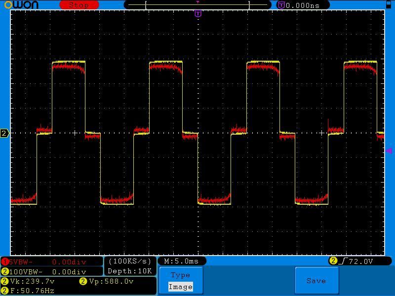
I don’t have an OEM shop transformer so your mileage may vary, but I do have a 9VAC (nominal) wall-wart style transformer. It generally gives a pretty good low voltage replica of the mains. I just plugged it into the 100W 240V outlet in the boot of my Toyota which uses the classic 3 step modified sine wave: 0V, +300V, -300V.
The Yellow trace is the high voltage inverter output, and the Red trace is low voltage transformer output fed into an R (about 10K from memory 110K):
There seems to be a bit of overshoot on the 0V mark on the Red. Interestingly, the transformer seems to be able to predict the future too! Note how the Red trace starts heading towards 0V before the Yellow trace. I don’t currently have a good explanation for that, but I guess the transformer is filtering out some of the higher frequency stuff.
I don’t have any of those shop CTs. Mine are all 333mV CTs and the smallest I have is a 20A. The maximum current I can draw from the 100W outlet in my boot is about 400mA, so that would result in an output signal of about 7mV, so I think it’d be a pretty noisy picture.
That picture shows a bit of l.f. droop - to be expected of course - but the h.f response must be heading well into the kHz region, because all I can see is a tiny bit of rounding on the leading corner.
The CT response certainly goes up into the low kHz region, but I too had very limited power available so couldn’t do an exhaustive test.
Sorry, @dBC just after sending post I have realized that with a CT we need lot of power to see anything. I will try to use and AC - AC voltage adapter. Thanks
Do you think that in a real case with some consume AC - AC adapter will modified a lot the shape ?
For example with a “special” load as a (compact or not) fluorescent lamp ?. (I mean, a inductive load, not a resistive load).
Could @dBC check what kind of shape of voltage have before and after the adapter if your car is powering a lamp ?
With resistive loads probably the shape doesn’t change. At less, as your picture (10K ohms)
@dBC I hope you have generated more curiosity on this matter
When I loaded mine up (with a resistive load) the peak-to-peak voltage sagged quite a bit (~40V from memory), but the duty-cycle changed (more ON time) to compensate, so that Vrms only dropped by about 1V.
[EDIT] I meant loaded up the inverter… not loaded up the transformer. The transformer only ever connected to the 10 110K R.
I have understood that you conect your 230VAC output with a resistive load, and the input of the transformer.
Also conect a 10K resistance to the output of the AC transformer.
What I want to know is about how the AC transformer changes the shape of the “modified sine wave” when you see both thought an oscilloscope.
Two questions:
why do you think that it is necesary to put the 10K resistance ? To check the voltage output of the AC transformer we don’t need anything, do we ?
could you check the wave in the input of the AC transformer vs the wave in the output of the AC transformer with ANY load in the AC transformer and a inductive load (lamp) in the input of AC transformer (or, the same point, output of your car’s inverter) ?
Thanks a lot
I think your screenshoots could be publish by an administrator just in case someone is using any hardware from openenergymonitor with a solar inverter or similar, couldn’t them ?
May be someone can use and AC transformer to calculate True RMS of and inverter output.
That’s what the transformer was soldered to at the time I did my tests (actually, I was wrong when I guessed 10K, it was actually 110K, now corrected in the earlier post).
I’m not sure exactly what you mean by “inductive load (lamp)”, but I did try it with an ordinary resistive incandescent bulb, and a laptop charger (presumably a SMPS). None of the loads I tried made a significant difference to the output of the inverter, other than variation in the peak-to-peak voltage, and a corresponding change in duty cycle. It appears that the inverter tries harder to regulate Vrms than it does Vp2p and it does that by varying the on-time. With all loads I tried, those same sharp 90 degree corners were present, and the transformer did as good a job as it could mimicking them. You can see how good a job in the picture above. Apart from some amplitude changes and some corresponding duty cycle changes, the picture always looked like the one above with the loads I tried (both Yellow and Red traces).
Are you sure your solar inverter is a simple 3-step modified sine wave like above? I guess it’s adequate for charging your laptop which I imagine is what most people do with that outlet in their boot, but I wouldn’t have thought it ideal for running an entire house. Anything that’s looking for a clean zero-crossing like SSRs etc. is likely to get into trouble with that extended (and very variable) 0V run. I’m not sure if AC motors would enjoy that square wave fed to them, maybe someone more experienced in them than I am can comment.
At any rate, lugging all the test equipment down to the car is non-trivial, so that’s probably all I’m able to contribute at this stage. Good luck with your project.
What i DONT want to know: how the output of the inverter changes after changing the load in the inverter (it changes duty cycle, Vp2p, etc…)
What I want to know: how the output of the TRANSFORMER changes after changing the load in the inverter
Thanks a lot for your test, i will wait for your screenshoots.Probably a compact fluorescent lamp will change shape of the voltage or of the current of the inverter. What kind of shape could we see after the AC transformer ?
People usually have pure sine inverters, but if you want to check them, or want to see your modified sine wave or want to MEASURE the power that you are pulling from your inverter it will be great to confirm that after and AC transformer the shape of the wave is the same, more or less.
Don’t you think that dBC has already answered that question: [quote=“dBC, post:13, topic:1532”]
… and the transformer did as good a job as it could mimicking them. You can see how good a job in the picture above. Apart from some amplitude changes and some corresponding duty cycle changes, the picture always looked like the one above with the loads I tried (both Yellow and Red traces).
[/quote]
He is saying that although the shape of the wave changed, the difference between the shape at the input to the transformer and the shape at the output was always very nearly the same - as his earlier picture showed.
I agree with you. But I am not sure if an inductive load will modify the inverter wave a lot, and after, transformer “smooth” that shape.
That is my last doubt about this.
Those compact fluros you referenced have small SMPS in them, so wouldn’t appear as inductive. I’d expect them to appear roughly similar to the SMPS in the laptop charger I tried… very non-linear and probably a little capacitive at the fundamental.
The extremely lightly loaded transformer that the inverter is feeding is probably already quite an inductive load, and I noticed no significant change to the output of the inverter when I plugged it in.