First post here, so a quick hello: I’m Kit, I design small monitoring boxes for rural water and power setups. This one is for a pond-fed water supply where the pump can fail silently: you find out when the taps are dry, sometimes days later.
The failure modes worth catching:
- pump seized or breaker tripped: no current, no water
- float switch stuck open: pump runs and runs dry
- float stuck closed: pump never starts, no water
- intake or strainer blocked: pump runs, nothing moves
- pond level below the intake: pump runs dry
The idea. One mains-powered ESP32 watching two signals.
-
Pump current, via an SCT-013 CT clamp on the pump feed. Variant warning: they ship in different output flavours. Get the 1V-output version for the ESP32 ADC; the 100A/50mA one needs a burden resistor.
-
Water level, via a JSN-SR04T-2.0 waterproof ultrasonic looking down a short PVC guide pipe over the water. The guide pipe quietly fixes most of what makes outdoor ultrasonics flaky: surface ripple, weeds, condensation on the transducer face.
The logic. Two states (idle / running) plus persistence: N bad samples over M minutes before anything trips. The rule I care most about: any sensor fault, lost echo, or out-of-range reading holds the alarm state; nothing clears it except the condition actually going away. My first firmware draft cleared the alarm when the ultrasonic lost its echo (pump running blind = worst case), and a simulation caught it, not me. A watchdog that goes quiet when it loses sight is worse than none.
Open questions for anyone who has done outdoor level sensing:
- Cold: the site gets hard frost and the pond ices over. Does the PVC guide pipe make icing better or worse? Has anyone run a heated or vented variant?
- Anyone feeding a “pump running” plus “level” pair into emoncms, and how did you model the alarm (feed process vs external script)?
Parts are about £30 all in; firmware is plain Arduino with a local buzzer and LED in v1 (Wi-Fi push later), no cloud dependency. Happy to write up the wiring and enclosure cut list if it is useful to anyone.
Welcome, Kit, to the OEM forum.
A couple of observations regarding your proposal:
- What is the pump current - running, inrush and stalled? You need to know these numbers to get the right c.t. The inrush current - or worse, the stalled current - will be several times the running current so you will need to clamp the output of your c.t. so as to not damage the analogue input that’s measuring the c.t. voltage.
- The only experience I’ve had of ultrasonic level sensors is in enclosed tanks (of beer) so not a lot of help – keeping it cool was the problem, not icing. I would expect a PVC pipe would make very little difference, once ice forms it would be a solid plug and the true water level could fall and you’d never know. In any case, you need to have a slow bleed of air in/out of the guide pipe - otherwise you might a well measure the air pressure in the pipe (which I believe is how the water level is sensed in automatic washing machines) and temperature would affect this too, so not an easy solution.
Robert, thanks for both of these. The c.t. one caught a real gap.
Current side. As drafted, the front end is too casual: tip straight to GPIO34, no bias, no protection. Fixing that before anything gets soldered:
- Measure the pump first: running current with a clamp meter, and stalled/start current off the nameplate (or measured, if the plate is gone. It is an old pump and I don’t have its numbers yet).
- Pick the c.t. rating from running current, design the front end against the stalled number.
- Front end: mid-rail bias, series resistance, and Schottky clamp diodes to the rails, so a start or stall spike clips instead of reaching the pin. I’d rather lose a reading than an ADC.
The firmware only needs relative draw at runtime (it auto-calibrates baseline vs running), but the parts still need the absolute worst case. So: measurement first.
Do you have a preferred protection arrangement for ADC inputs fed from c.t.s? If there is a house pattern here, I’ll copy it rather than invent mine badly.
Icing. Agreed, and I’ll stop pretending it’s a sensing problem. What I’ll do instead:
- Vent the transducer end so the pipe can breathe. Your point about the air column is fair: with no bleed it is a pressure gauge, not an echo path.
- Cheap thermistor plus “reading pinned for days” = level goes advisory in frost, so it degrades instead of false-alarming.
- The current side stays the winter watch. Pump commanded plus no current is the failure that matters at -20, and it does not care about ice.
Winter level probably is a different sensor class. I don’t have a pressure/hydrostatic story that survives the effort test yet, so v1 ships with the limitation documented rather than hidden.
Bench and site numbers will go up here once the build exists. This is exactly why I posted before building, so: appreciated.
You won’t go far wrong by copying what we do – basically, a standard input circuit you find in any audio amplifier.
Note: From what I remember about the ESP, the centre of the input range of the ADC is not necessarily the mid-rail voltage, so the two bias resistors might not be equal. Check the data sheet.
I had a thought about ice: If the pond is deep enough and the pump intake low enough, icing might be delayed enough to allow water to be extracted. In this case, a submerged pressure sensor at the level of the pump intake will give you the head of water, even if there is a layer of air between the surface of the water and the underside of the ice.
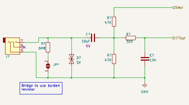
Copying it then. Here’s my adaptation for the ESP32, in case it’s worth a look before anything gets soldered:
- Input: the 5 V bidirectional clamp across the jack, as drawn.
- Sleeve to GND; tip goes through a 10 uF coupling cap (+ toward the bias node) into the bias node.
- Bias: 15k top / 10k bottom from 3V3, so the node sits near 1.3 V.
- From the bias node: 3k into the pin, 10 nF to GND at the pin (your RC), plus the Schottky pair at the pin.
On the ADC centre: you called it. The datasheet’s recommended window at 11 dB attenuation is about 150-2450 mV, so the usable centre is nearer 1.3 V than mid-rail. Equal resistors would have sat 350 mV high and eaten the top of a full-scale swing.
One thing I want to understand before copying it: what is the 5 V clamp across the input defending against, mains-side transients or a CT open-circuit spike? I want to know what I’m relying on, not just mirror the drawing.
Ice: pressure sensor at intake level noted as the honest version. v1 still ships with frost documented rather than solved; the current side is the winter watch that doesn’t care about ice.
Appreciated.
Stop and think - the answer should be obvious. If not, read the data sheets for the c.t’s you considered using.
In general NEVER copy something without fully understanding what it is and what it does. You can get into big trouble if you don’t understand and adapt – as you’ve already seen with the ADC voltage range.
Stopped and thought, then went back through the datasheets. Here’s what I came back with:
The clamp is for the c.t.'s own open-circuit spike. Not mains-side transients: the secondary is galvanically isolated from the primary, so grid voltage can’t reach the input. What the input gets is induced current. The dangerous case is that current with nowhere to go: jack unplugged, or a lead broken, while the c.t. is still clipped around a current-carrying conductor. The secondary then drives into an open circuit and the voltage rises until something gives. The 5 V clamp is the something: a defined ceiling across the jack, and a path for that current.
What the trail says, once I actually read it:
- Safety note: never open-circuit a c.t. while it’s on a current-carrying conductor; it is always safe to short-circuit one.
- The SCT-013-000 report: current units have a single TVS across the secondary (earlier revisions had 22 V zeners, then SMT zeners). That limits the unburdened output to a value safe for the transformer. It defends the c.t.'s insulation, not my input. The synopsis is blunt about it: the unit is capable of developing sufficient voltage to fully drive a 5 V input.
- The voltage-output variants carry their own burden, so they can’t be open-circuited this way. But I can’t design around which c.t. someone plugs in, so the input side has to stand on its own.
So the chain in my design is: c.t. internal TVS (if fitted), jack clamp, coupling cap, bias, 3k + 10 n at the pin. Each stage only has to handle what the one before it lets through, and the jack clamp is there because I can’t rely on the insides of a c.t. I didn’t build.
Rule taken, and this project has now taught it to me twice. The ADC centre was the first time. A proven circuit goes in only once I can say what each part is defending against. If I can’t say it, I don’t understand it yet, and I’m just hoping the drawing is right.
I’ll be back with the pump’s running/start/stall numbers and a front end sized against them, before anything in this thread gets soldered.
No, it is both – up to a point.
True, but a high current – sustained or a spike (say blowing a fuse) – will get through the c.t. until it saturates, then (if it is sustained - as you get with inrush current if you size the c.t. for the running current) as it comes out of saturation on one half-cycle and goes into saturation on the next, the rate of change of current (dI/dt) gets very large. What does the secondary winding make of this?
Both, then — and here’s my attempt at saying the second one properly. I found where you’d drawn it before, in the SCT-013 50A thread: “the output flattens as the core saturates, but then the flux changes rapidly on each half-cycle so high voltage spikes are produced.”
The way I’d say it now: while the core is saturated it stops linking the windings, the secondary can’t deliver the transformed current, and the output flattens. On each half-cycle transition the flux has to recover its swing in a fraction of the time, so dΦ/dt goes through the roof — and the secondary voltage is just N·dΦ/dt: a spike, twice per cycle, for as long as the overcurrent lasts. Same thing in current terms: the secondary current steps from near zero back to the transformed value, and a winding turns a fast dI/dt into V = L·dI/dt.
What the secondary does with it, then, is throw a high-voltage spike back at the input, while everything is plugged in and looking healthy. Nothing galvanic is needed for that; the spike is made on my side of the fence. So the jack clamp’s job list is two entries, not one:
- the open-circuit spike (leads unplugged or broken while clipped on a live conductor);
- saturation transients from any current above the c.t.'s rating — inrush, stall, a fuse clearing.
And “up to a point”, read through a clamp’s eyes: a clamp is an energy barrel, not a wall. One event is what it’s for; a sustained stall keeps refuelling it. So the first defence stays sizing — pick the c.t. so running + start/stall currents stay under the knee where possible, then clamp what’s left.
The pump’s running/start/stall numbers are still coming, before anything gets soldered. That measurement now decides how often the clamp has to work for a living, not just the gain.
Quick update, closing the loop on this one.
A user on another platform ran the design on his own half-clogged pond pump. His numbers: pump current slid from 9.5 A clean down to 6.8 A as the strainer clogged, while the level sensor read fine the whole time. Vacuum at the flange measured 8 inHg (clean wants 1-2). New gasket, hiss gone, current back to 9.4-9.5 A across seven reads.
Two things worth saying plainly:
- Clamp-first was the right call. A falling level alone would never have flagged it; the current sag is what told the truth.
- The alarm catches the sag but can’t name the cause. Suction-air ingress and a clog look identical at the clamp. To get why, you need a suction pressure tap alongside the amps.
Free starter design (parts, mounting rules, test plan): The $35 Pump Watchdog - a free starter design
Happy to share the full pack too (firmware, the c.t. input stage from this thread, the bench drill).
And the open ask: I’ve written all of this, but I’ve never held the iron. If anyone here has a pump they can bench-test it on this winter, I’d rather put it in hands than keep polishing paper. Say so and I’ll send the parts list.