My 3 phase solar PV inverter is connected to a smart generation meter (used to calculate the feed-in & export payments I receive).
If I use a single phase sketch and hook a CT to each of the 3 phase inputs to this meter and then sum the results, I’ll get the total APPARENT power (VA) being generated (assuming vrms is the same on each phase) – or, that is my understanding from what I’ve read on this forum.
My question – does the smart generation meter measure real or apparent (VA) power? and is that what will recorded by an optical LED sensor on the meter?
Yes, provided you use the product of rms current and voltage (or don’t have an a.c. adapter and assume a voltage) to get VA. If you use “power” and you have an a.c. adapter, it will be hopelessly wrong.
Your smart meter will almost certainly read both real and apparent power, and indicate (unless it’s told otherwise) real power. And that is what the pulse output will be.
But as the grid power factor is likely to be inductive but nevertheless close to unity, I would expect little difference between real and apparent powers.
My understanding is that rms current is not available from the single phase sketch and that a modification is needed. How do I do that? Would any modification survive periodic sketch updates? Is there a how-to to link to?
Given I chose to use an ac adapter and also given we are talking about generation and, as you comment, the grid will be close to power factor=1, does this perhaps suggest the ‘hopelessly wrong’ indicated phase powers could be corrected somehow with a constant factor involving sin or cos 120 or 240 degrees? Presumably the power indicated on the phase with the ac adapter connected would not need correction?
My objective is to get a reasonably good approximation of total real power generated for input to the App MySolarPV and to display this on a small screen on the kitchen countertop and for other monitoring.
Current is available in the sketch, but it isn’t normally sent by radio. You would need to add it to the transmitted data, or probably easier and better, apparent power is also available, so replace “realPower” with “apparentPower”. It’s a relatively simple edit, there’s no ‘How-to’. And that way, you wouldn’t need to avoid updating the Pi - if that’s where the data is going. The emonTx sketches only get updated when you do it manually.
I wouldn’t like to say what happens there when the current waveform departs from a sine wave! (And I believe at least some inverters try to ‘fill in’ waveform distortion.) If you want to try that to check the accuracy, the factor is -½. It may be good enough if you have P.M.E. and the angles remain correct.
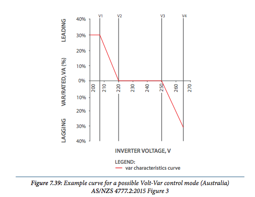
In some jurisdictions (like here in Queensland) it’s now a requirement that PV inverters generate some reactive power, so the assumption that real and apparent power out of an inverter are pretty much the same may not always be valid.
Presumably capacitive, expecting the consumer to clean up the generally inductive load on the system? If they (the inverters collectively) are too enthusiastic, it could get interesting.
If the voltage drops and inverter looks capacitive, it will clean up the supply: lower the circulating vars in the distribution transformers, improve the voltage regulation and reduce the losses, and the customer pays for it. It’s win-win for the electricity supplier.
But maybe Queensland doesn’t want that - I’d read that as they want the inverter to look like the rest of the system, presumably they’re worried about the voltage rising out of control?
Yes, with widespread PV penetration and 11kV feeders running backwards in the middle of the day, high voltage seems to be the biggest problem. The inverters are supposed to trip at about 257V (from memory) and then stay off for several minutes before ramping back up, but many installers left the inverters set at their default trip points which are often around 270V.
I’ve read that the 0.9 lagging is meant to compensate for the inverter’s natural characteristics. The following quote is about as close to an explanation I’ve found, but I’m not sure I’ve fully got my head around it. Maybe the “pages of maths” is required. Thoughts?
When an inverter exports it not only unloads the powerline (in itself causing voltage rise), as a source it has to raise its voltage above nominal to export. (Without going into pages of maths) the end result is, (warning generalisation), similar to a small capacitor bank being switched into the circuit at the tail end of the feeder. It causes a voltage rise out of proportion to the current injected.
Hmm.
I think there’s a big hunk of generalisation and lumping of two effects there.
Adding capacitors will raise the voltage because the system is inductive - in simple terms, it’s heading for a resonant peak. That in itself is nothing to do with inverters and PV. I hung a (controlled) capacitor bank on the 11 kV grid to compensate for dip when a large (3 MW) thyristor drive started up.
Feeding in locally will support the local load, thus reducing the current, hence voltage drop, in the feeders and distribution transformers further upstream.
What I think they mean by[quote=“dBC, post:9, topic:3282”]
It causes a voltage rise out of proportion to the current injected.
[/quote]
is the two effects are working together.