Measuring air change rates with CO2 sensors for heat pump heat loss calculation

So I’ve bought the 2017 version of the standard from EVS and it’s completely changed :exploding_head: so I may be back to square one with this…

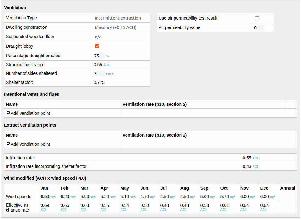
The nice equation for converting an n50 blower door result to a infiltration rate seems to have disappeared, there are no nice worked examples of different ventilation methods only the basic simple one and the equations and descriptions have otherwise got a lot more complicated. They cover a much wider range of internal air movements…

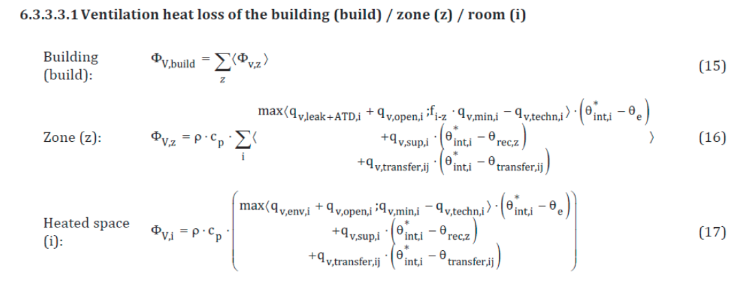
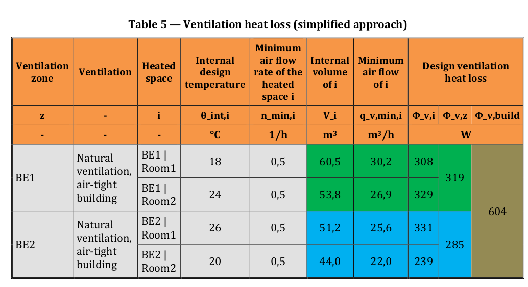
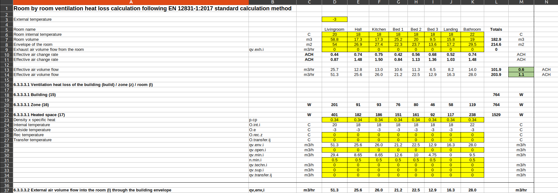
I think for buildings with natural ventilation it just says that you use the simplified calculation method which is the standard method used in heat loss calc.

Correction: After reading through the standard more thoroughly I realised I was wrong in my assessment that it suggests to use the simplified method for natural ventilation, it actually says that the standard calculation method is suitable for all situations and that the simplified method is only suitable for air-tight buildings without forced ventilation. The earlier 2003 standard for the n50 blower test conversion has also just been changed to a different formulation starting with the permeability test result instead.

There’s a table B.7 that states that minimum air change rate default values should be 0.5 ACH and secondary / internal rooms 0.0 ACH… but then there’s another table B.12 “Air change rate, default values for simplified methods” which states in the absence of national data:

  • Heat loss of single rooms: 0.5 ACH
  • n50 < 3: yearof construction >= 1995, buildings with tight windows: 0.25 ACH
  • n50 > 3 but <=6: year of construction <1995: 0.5 ACH
  • n50 > 6: year of contstruction <1977, buildings with obvious leakages: 1.0 ACH

So not very helpful for my n50 of 10 as that would suggest using 1.0 ACH “in the absence of national data”.

I guess that will teach me to avoid assuming that the standards will not have radically changed between versions!

Still. 0.25 to 1.0 not 3.0

1 Like

True!

Richard Jack of BuiltTestUK spotted an interesting aspect that I missed about the new standard that it seems to effectively halve the ventilation heat loss at the point when you add up all the rooms to calculate the zone or building total… it’s a bit strange as it suggests that you need to size the radiators for the room values but the whole house requirement would then be that much lower…

The factor that halves this is the f.i-z factor in equation 15, or the selection of qv.leak instead of qv.env.i (whichever is largest in that max selection). This same factor is present in the simplified method.

Here’s an example of what this looks like in the supplementary simplified calculation example available in EN12831-2:

As you can see they did indeed halve the individual room heat losses here to give the zone and build totals!!

A possible reason for this factor that halves the vent heat load as you add up all the rooms is that there’s an orientation factor earlier in the standard calculation that doubles the infiltration air volume rate and perhaps this is there to account for wind load on one side of a building that results in higher heat requirements in those rooms? Perhaps this later halving is then to average it all out for the whole building?

Strangely in the simplified example given it effectively halves the air change rate from an n.min of 0.5 to 0.25 for the whole building, which is then really a bit low for air quality… and certainly below part F regulation requirements for the whole building… but then it is just an illustrative example.

Correction to my post above: After reading through the standard more thoroughly I realised I was wrong in my assessment that it suggests to use the simplified method for natural ventilation, it actually says that the standard calculation method is suitable for all situations and that the simplified method is only suitable for air-tight buildings without forced ventilation. The earlier 2003 standard for the n50 blower test conversion has also just been changed to a different formulation starting with the permeability test result instead.

Example spreadsheet calculation using the EN12831-1:2017 standard method:

Here’s my attempt so far to implement the standard calculation method:

EN12831_2017_ventilation_calculation.ods (20.4 KB)

So this does perhaps give a calculation basis for lower whole building ventilation heat loss… E.g the result for our house (whole house) with part F continuous extraction levels + natural ventilation is 0.6 ACH! But individual rooms are calculated to double that ~1.1 ACH…

1 Like

Maybe it’s assuming that the emitters are all individually controlled, so can be sized to meet the maximum reasonable demand in an individual room (e.g. when the window is open, or the wind is strong) whilst the heat demand for the whole house will average out variations between individual rooms and account for heat lost from one room into another?

2 Likes

Yes exactly, that’s what it looks like. it’s a good thing from the whole house heatpump sizing perspective, but more unusual from a heatpump control perspective. Would require increasing flow temp to whole system so that rads in wind affected rooms get their input whilst turning off/down rads in the sheltered side of the house… it’s a possibility at least

I don’t understand enough about HP control to understand why you’d want to increase the flow temperature?

What I would really love to know is how these calculation guidelines that are found in the standards were ever validated in actual real-life scenarios. What’s the precision/accuracy of the predictions when applied to a suitable group of houses (not only newly built ones, but rather a representative crossection) Sure, the physics behind it is quite simple, but I’m having a bit of a hard time trusting results from a purely analytical evaluation, especially for older properties. Is there a section in the standard that elaborates on validation?

1 Like

It’s probably more for larger buildings with district heat etc. Weather condensation runs “a touch hot” and the TRVs modulate down your 20%? margin.

In UK shoeboxes with heat pumps you pop the door open for balance if to warm/chilly. :slight_smile:

1 Like

Not as far as I can see, there is a Bibliography that lists 25 other standards, though none specifically mention ventilation…

I did notice this paper that was interesting: https://proceedings.open.tudelft.nl/clima2022/article/download/134/191

"The current method for the calculation of the design heat load, according to the EN12831-1, is a static method and tends to overestimate the heat load. This research based on 50 in-situ measurement cases suggest indeed an oversizing between 25% and 100%! "

It discusses one of the reasons for the observed curve that we also see in the heatpump heat demand tool on some systems. Higher wind speeds in milder weather…

1 Like

25 - 100 % overestimation is huge. Didn’t matter for gas boilers as they can modulate much further down but this is quite critical for heat pumps. Add on top the internal gains that are intentionally left out and it’s no wonder there are so many oversized systems out there. I really think the whole industry needs to shift their thinking. The main driver behind the heat pumps is a move towards sustainability, which should include using a heat pump that is not massively oversized because some unrealistic guidelines.

Hopefully future technological innovations will lead to a better modulation range, which would significantly alleviate the problem.

1 Like

Yes, and we’re seeing some heat pumps with 2-3x oversizing…

I guess that’s what the industry is used to. The gas boiler I replaced had 24 kW. Another offer for a new gas boiler was sized at 17 kW. Now I have a 10 kW heat pump and would only need 7 kW. People (and installers) just need to get comfortable with those much lower numbers and also get rid of the notion to oversize “just in case”.

1 Like

SAP 2012

Thought it might be interesting to compare EN 12831 to other calculation methods. A while back now I helped CarbonCoop build a SAP 2012 assessment tool and that has a section for estimating air change rates that I should probably have paid more attention to at the time!

Here’s a screenshot of the ventilation section in my more recent minimal SAPjs implementation of what used to be called MyHomeEnergyPlanner:

Try the tool here: https://openenergymonitor.org/sapjs/

SAPjs source code: https://github.com/TrystanLea/SAPjs/

OpenBEM underlying model code: https://github.com/TrystanLea/openBem

The SAP 2012 calculations are split into infiltration (air movement through the building structure) and ventilation.

Basic structural infiltration rate:

1. Number of floors

infiltration = (number_of_floors - 1) * 0.1

2. Dwelling construction

if timber frame:
    infiltration += 0.25

if masonry:
    infiltration += 0.35 

3. Suspended wooden floor

if suspended wooden floor:
    if unsealed:
        infiltration += 0.2
    if sealed:
        infiltration += 0.1

4. No draught lobby += 0.05

5. Draught proofing

+= 0.25 - (0.2 x % draught proofed / 100)

6. Shelter factor

shelter_factor = 1 - (0.075 * data.ventilation.number_of_sides_sheltered);
infiltration = infiltration x shelter_factor

7. Wind factor

windfactor = windspeed / 4
infiltration = infiltration x windfactor

Example (My house):

A 2 story house, masonry, solid floor, with draught lobby, 75% draught proofed, sheltered from 3 sides and at a mean January wind speed of 6.5 m/s

infiltration before shelter factor = 0.1 (floors) + 0.35 (construction) + 0.25 - (0.2 x 0.75) = 0.55 ACH

shelter_factor = 1 - (0.075 x 3 sides) = 0.775
infiltration after shelter factor = 0.55 ACH x 0.775 = 0.43 ACH

windfactor = 6.5 m/s / 4 = 1.625
infiltration after wind factor = 0.43 ACH x 1.625 = 0.69 ACH

From air permeability test

The SAP 2012 calculation also has the option to enter an air permeability blower door test value. Ours was 8.9 m3/hr/m2 without taping up the extract vents and stove.

air permeability = 8.9 m3/hr/m2 

This gets converted to air changes per hour at 50pa by multiplying by the external envelope area and dividing by the dwelling volume which in our case is:

8.9 x 240.2 m2 / 205.8 m3 = 10.4 ACH @ 50pa

This divide by 20 approximation is then applied:

10.4 / 20 = 0.52 ACH

We then return to step 6 the shelter factor above and apply the wind speed correction:

0.52 ACH x 0.775 (3 sides sheltered) = 0.403 ACH
0.403 ACH x 6.5 m/s / 4 = 0.65 ACH

Which is pretty similar to the first approximation I guess! Both of these figures are in the ball park of what I measured (or estimated given that some estimation is still required with the measurement) using the CO2 sensor approach of around 0.6 ± 0.2 ACH for January. The average wind speed in January according to the MetOffice for our area was 6.8 m/s.

At least SAP 2012 confirms that CIBSE pre-2000 figures are way out!

Wind speed correction

The wind speed correction in SAP 2012 is interesting but I also wonder if it can overestimate heat loss. Here’s the wind speed and temperature for our area in January, there is a rough correlation between wind speed and outside temperature, milder weather generally brings higher winds, convenient for heat loss (but less convenient for wind generation when you need it…).

Correlation (each datapoint is an hour):

Does the SAP wind speed factor work for higher wind speeds? E.g during the 20th to 24th of January storm, winds were around 12.5 m/s this would suggest a multiplication factor of 3.1x which if applied to 0.403 ACH from the base blower door rate = 1.26 ACH… and I measured an average of ~1.2 ACH using the CO2 sensing! not bad at all! :slight_smile:

1 Like

PS: I think if you don’t include a high % draught proofed and high shelter factor which I wouldn’t say is particular true for our house the estimated air change rates end up being a bit high I think via the SAP 2012 method.

If you also add extract ventilation points on top of that and stove flues the air change rates may be overestimated a bit more. I had added a 20m3/hr stove and 10m3/hr extract point when I did my assessment example a few years ago, I think based on suggested values in the SAP documentation. These push up the January average to 0.9 ACH. I think in reality our stove must have a much better seal than that and we dont use it anyway so it’s all closed off and not drawing air for a fire. The intermittent extract ventilation is probably not on long enough to be significant…

Another heat loss model that might be worth looking at is the Home Energy Model. They give quite a lot of detail about how they’ve validated their model. For example, here’s what they have to say about infiltration and ventilation:

Thanks! Is this the new SAP? Do you know the history?

There’s a good overview at

But google shows lots of other resources as well …

There’s also

1 Like

Thanks @djh this is very similar to the SAP 2012 implementation which conveniently saves me a whole lot of new learning :slight_smile:

One of the main differences is the divisor table, giving different factors to divide the n50 value, other than divide by 20.

The shelter factor equation and the wind factor equations as used in SAP 2012 are the same. The result from our house would go up slightly if I used Normal (Country with scattered wind breaks) to around 0.74 ACH.

There’s a usefully long piece on flues and chimneys etc…

I’ve now written the above research into air change rate calculations methods into a documentation page here https://docs.openenergymonitor.org/heatpumps/air_change_rate_calculations.html. Please feel free to suggest improvements.

4 Likes