So are you just running the old 1.8.19 version for simplicity / sanity… ![]()
![]()
I’m using both 1.8.19 and 2.3.1.
The only annoying “feature” of 2.3.1 that I’ve noticed so far is it won’t ignore its own editor, whereas 1.x will. I prefer Notepad++ any day, even though I run under Ubuntu.
Life’s too short to try to set up CodeBlocks or something like that, even though I did use if - mainly for the code completion - during the early stages of writing emonLibDB.
Hi Robert, Yes,… to to prefer notepad++ as an editor,… I wrote a whole bunch of ASM 6502 stuff with Notepad++
Although, like yourself I run on a ubuntu system,… with some vbox windows clients to run the windows’y things I need.
So my fundamental question then is can you compile emonTx4 with 2.3.1,… the docs say no,… as there are too many ‘issues’,… is this correct?
Tx
Rgds
Mark
I haven’t found any other issues. Once I got to the point where I could compile and test emonLibDB, I’ve used V2 almost exclusively for this. I’ve only been compiling the “max” example sketch, most recently with V2.3.1 while looking to add the precision reference voltage to calibrate the ADC (unusable - it’s buried beneath ripple) and a “phasecal” non-automatic setting mode (seems to work well) to emonLibDB.
That’s a shame - I always thought that was a nifty addition. What’s the peak-to-peak of the ripple in ADC counts when sampling the reference? And what’s the nominal expected value in ADC counts? Any idea where the ripple is coming from?
1 Like
@Robert.Wall @TrystanLea A bit off topic but …
Looking at the emonPi2 schematic around the MCP1501 precision reference, it might be possible to reduce noise on the VREFA line, by moving C28 (2.2u) so that it connects directly from VREFA to ground. This can be done without any PCB changes by changing R42 to 10K (from 10R) and changing R37 to 0R (from 10K). This will add a ~14Hz LPF to the VREFA line and considerably reduce its impedance to ground from 5K ohm to 5K ohm in parallel with 2.2µF.
The same is applicable to the emonTx4 but with different component designators -
C21 instead of C28, R35 instead of R42, R30 instead of R37.
The only caveat would be that to maintain accuracy, the 2.2µF capacitor shouldn’t have any significant DC leakage current.
I don’t know if this will help!
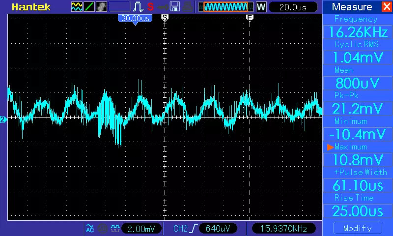
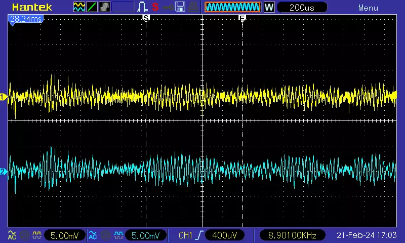
Some pictures from the “dark green pcb” emonTx4 - AREF (900 mV) :

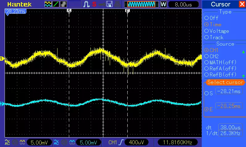
with 1µF tantalum electrolytic from AREF to GND - about 2 mV p-p:
Here’s what the 1 µF tantalum on AREF does to the numbers (before/after):
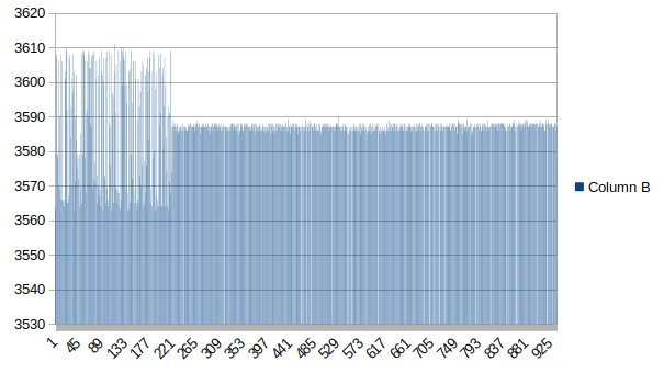
The spread of values after:
| 3585 | 3586 | 3587 | 3588 | 3589 | 3590 |
|---|---|---|---|---|---|
| 13 | 101 | 201 | 156 | 14 | 1 |
Ignoring the outlier, those represent a spread of ± 2 (±0.056%) so I’m quite content to recalibrate every mains cycle with this number.
I’m not at home at the moment so I can’t check, but from memory it’s not on the supply – I’m almost certain that’s the first place I looked.
I think I’d be inclined to adopt a configuration a bit closer to the data sheet, then divide the output down as necessary. I don’t think the noise contribution from 2 10kΩ capacitors effectively in parallel would be significant at 900 mV.
That’s impressive to come up with those results so quickly!
So a capacitor from the VREFA line to ground improves things significantly.
I didn’t think that the MCP1501 or the divider resistors would be the source of the noise. My guess was that the VREFA track to the ADC was picking up digital noise from the rest of the PCB.
In the present configuration, the impedance of the track to ground is quite high at 5K ohm. It would only take a small stray capacitance and a fast voltage edge on another track to couple noise into VREFA.
Adding a reasonably sized capacitor to ground on VREFA as I described gives a low impedance to ground, and prevents the coupling of HF noise.
Low impedance to ground on the VREFA track could also be accomplished by driving the track from a precision op-amp after the divider, but would require PCB changes. The inclusion of the (possibly expensive) precision op-amp also introduces an error source in VREFA.
What data sheet configuration were you thinking of?
Not true - they came from a PM sent to Trystan early last month.
The “basic application circuit” shows an output load capacitance of only 0.1 nF. We don’t know the exact output stage configuration inside the MCP1501, nevertheless the arrangement we have just doesn’t look right. In the example with a 2.2 µF capacitor, it’s decoupled with a 50 Ω resistor. To me, it has the scent of the 2.2 µF and 10 Ω has destabilised the feedback loop inside the MCP1501.
I agree. You can see on the data sheet that the output starts to ring with >1nf to ground (figs 3-26, 3-29). That’s another reason to put the 10K (R42 was 10R) in series with the 2.2uF.
We’ll only know with certainty when somebody does the necessary change. I’m not prepared to do a software fudge and slow the sampling rate in the library in order to sample the reference along with every set of voltage and current samples and give up processing time to average the numbers, when the hardware should have been done right to begin with…
I unfortunately missed this issue when developing the hardware, it’s on my list to get up to speed on this. Thanks to @Robert.Wall for all of your effort looking into this and correspondence via PM.
@TrystanLea
As a first step, you could try the changes suggested (changing two resistor values, no PCB changes) to see if they help …
These changes also move the 2.2uF capacitor so that it is not ~directly connected (10R in series) from the MCP1501 output to ground. This removes any possible tendency for it to oscillate with a large capacitive load.
1 Like
Some more pictures:
No additional capacitor across AVref. Yellow: AVref, Blue: 3.3 V:
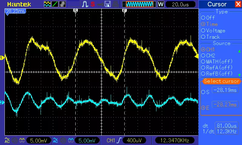
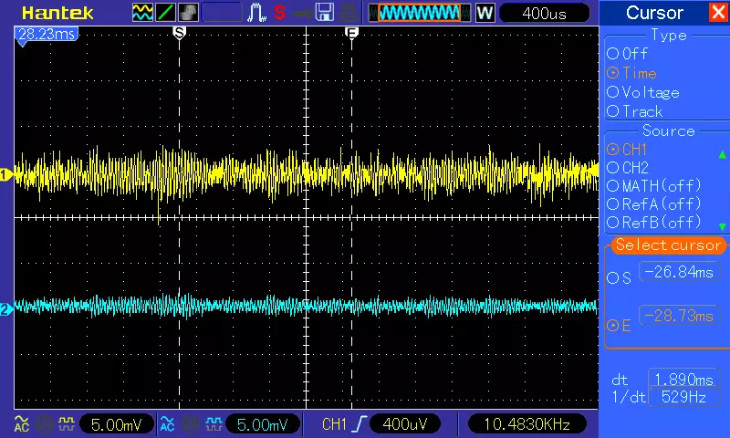
1 µF tantalum capacitor across AVref. Yellow: AVref, Blue: 3.3 V:
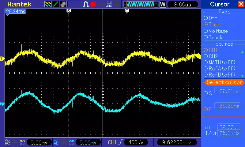
As above, different timebase:
4.7 µF tantalum capacitor across AVref. Yellow: AVref, Blue: 3.3 V:
As above, different timebase:
The guilty party is positively identified – it is indeed the 2.2.µF capacitor, but we all knew that anyway. Simply removing it gets rid of most of the trouble, on both VREFA and the 3.3 V supply.
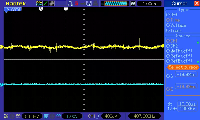
(Ignore the blue trace).
Removing the capacitor (and only that) looks OK to me.
Looking at the count coming out of the ADC, the spread of values is:
ADC   number
3567	0
3568	0
3569	0
3570	2
3571	9
3572	101
3573	145
3574	93
3575	19
3576	0
3577	0
3578	0
There are no outliers outside this range as far as the limits I’ve put in the library at the nominal count for 0.9 V ±2%, i.e. 3530 to 3675.
0.9 × 4095 / 3573 = 1.0315 V, so my 1.024 V internal reference is 0.73% high.
3 Likes
Robert,… Just trying to get the modified thresholds incorporated into the code…
I have to this end created a ‘mint’ environment with arduino 1.8.4… followed the ‘how to’ stuff,… and I can now compile without issue. ( all the ‘board issues’ I had, went away )
One complication is I am now trying also trying to compile a 12 CT, set of code,… using the EmonTx4_12CT_rf source.ino file,… and unless I’m missing the obvious I cannot find references to EmonLibCM_acPresent() or acDetectedThreshold…
Are you able to spread any light on this…
Many Tx
Mark
I don’t understand your question.
I’ve never published a sketch for the emonTx4 using emonLibCM - that’s obsolete as far as the emonTx4 and 12 current inputs is concerned. If it’s Trystan’s sketch on Github, can you give me a link? Searching for the file name you’ve given returns nothing. It also doesn’t make sense to try to use emonLibCM with a 12 current inputs emonTx4, because emonLibCM can only handle 6 - one voltage and 5 current - analogue inputs.
You probably need to download emonLibCM and emonLibDB, and start with the documentation.
acDetectedThreshold is on line 215 of emonLibCM.cpp, and line 283 of emonLibDB.cpp
EmonLibCM_acPresent is on line 424 of emonLibCM.cpp, it is obviously not part of emonLibDB. The equivalent is on line 566 of emonLibDB.cpp
sorry Robert, ( I changed from the original name when I saved it locally ),… I was just following this link for the Additional 6CT’s order to compile for 12 CTs
This is the link I have used,… following the EmonTx4 expainsion boards section for the emonTx4 docs.
2. Using the Arduino IDE, open the `EmonTx4DB_rf` firmware example. Navigate to:

File > Examples > emonLibDB > Examples > EmonTx4DB_rf
I also found this text with the docs
While the EmonTx4DB_rf firmware example does not use all of the libraries listed (it just needs emonLibDB and RFM69_LPL), it is worthwhile installing them all so that you have the capability to compile all EmonTx4 firmwares.
So what is the objective now? Are you back to this:
If so, then it’s decision time: If you never want it to fall back to using a fixed 240 V, and I can’t see the point if you’re using the same voltage as you’re measuring for power, then you don’t need acPresent and if you’re not using it, there’s no need to change the threshold - it will use whatever voltage it gets to calculate real power until the d.c. fails at around 100 V and everything stops. And you can use the example sketch you got with the library pretty much as-is - just remember it’s one of three demonstration sketches so the three together illustrate the use of every API call there is. You only use the bits you need to provide the information you want.
If you want to use a different sketch, then I’ll think a bit more.